Documentation Index
Fetch the complete documentation index at: https://docs.cadcamfun.xyz/llms.txt
Use this file to discover all available pages before exploring further.
CAD Editor
The CAD Editor is the heart of the application, where you can create and modify 2D and 3D models with a wide range of drawing tools and parametric features. This section explores in detail all the features available in the CAD Editor.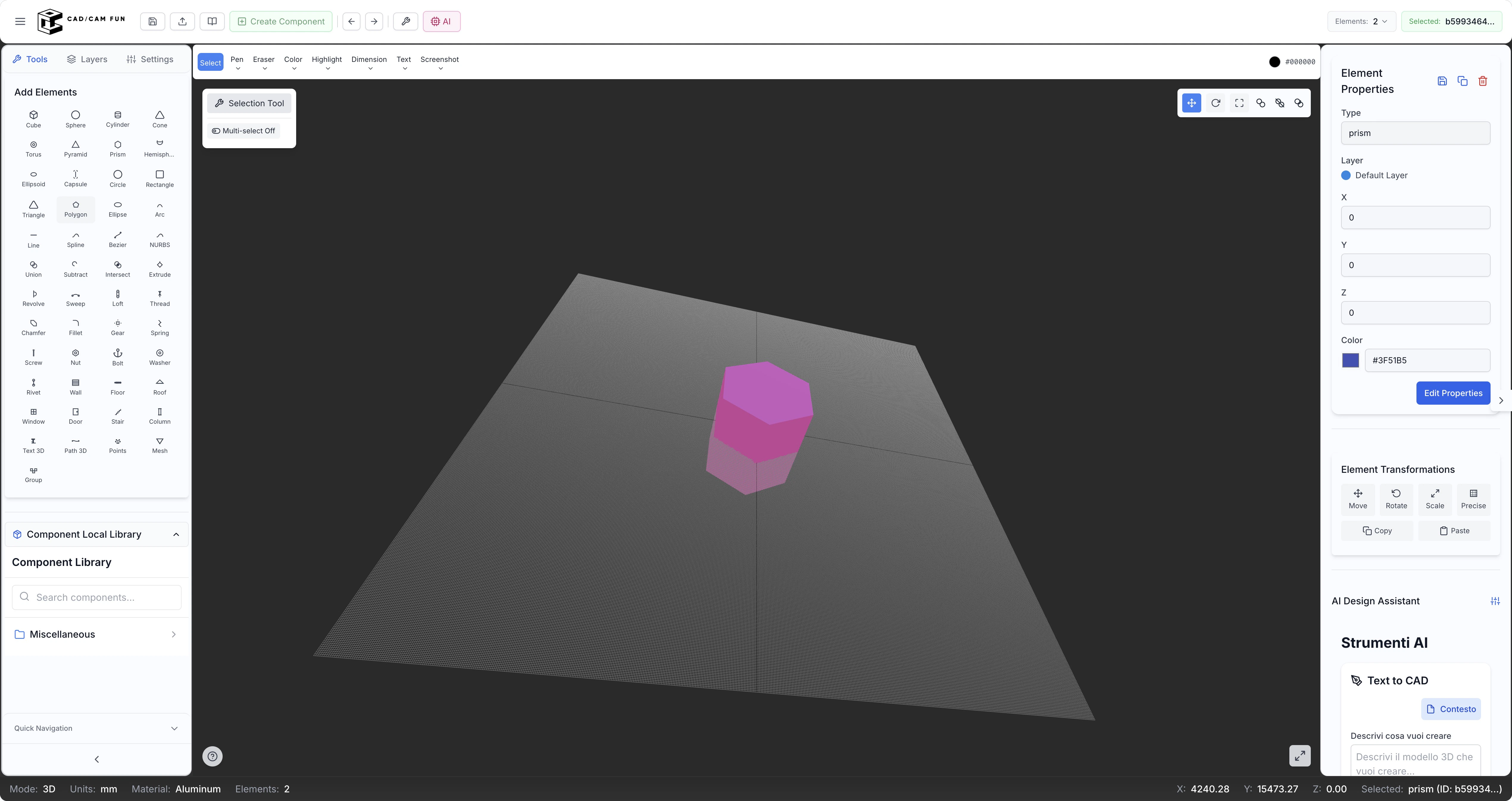
CAD Editor Interface
When you open the CAD Editor, you’ll find yourself in front of a complete interface composed of several functional areas:Top Toolbar

File Menu
File Menu
Edit Menu
Edit Menu
View Menu
View Menu
Tools Menu
Tools Menu
Quick Access Buttons
Quick Access Buttons
Library Button
Library Button
Import/Export Button
Import/Export Button
Left Sidebar
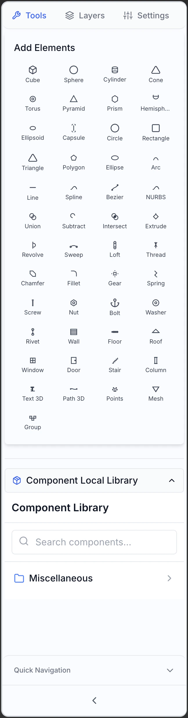
- Tools
- Levels
- Settings
Base Shapes
Base Shapes
- Line: Draw straight line segments between two points. You can specify exact length and angle, or draw freely. Use Shift key to constrain to 45° angles.
- Rectangle: Draw rectangles and squares specifying two corner points. Additional options for rounded or chamfered corners.
- Circle: Create circles with various methods: center-radius, diameter, three points, tangent to two elements. Essential for many mechanical constructions.
- Arc: Draw circular arcs with flexible definition methods: three points, center-start-end, start-end-radius, etc.
- Ellipse: Create ellipses and elliptical arcs specifying center and axes. Also for organic shapes and projections.
- Polygon: Generate regular polygons with a specified number of sides. Options for inscribed or circumscribed relative to a circle.
- Polyline: Create a series of connected line segments.
- Spline: Draw smooth curves through control points. Ideal for complex and curvilinear forms with continuity of curvature.
- Point: Create reference points.
- Text: Add text and annotations.
Modification Tools
Modification Tools
- Fillet (Round): Rounds angles between lines or surfaces.
- Chamfer (Miter): Creates angled chamfers.
- Offset: Creates parallel copies of curves or surfaces.
- Extend: Extends curves to a boundary.
- Trim: Divides curves at specific points.
- Join: Combines separate but connected curves.
- Divide: Separates curves into equal parts or at specific points.
Dimensioning Tools
Dimensioning Tools
- Linear Dimension: Measures horizontal or vertical distances.
- Aligned Dimension: Measures distances in any direction.
- Angular Dimension: Measures angles between lines or surfaces.
- Diametral Dimension: Measures diameters of circles or arcs.
- Radial Dimension: Measures radii of circles or arcs.
- Technical Text: Adds standardized annotations.
- Symbols: Inserts technical symbols (tolerances, finishes, etc.).
Transformation Tools
Transformation Tools
- Move: Moves selected elements.
- Rotate: Rotates elements around a point.
- Scale: Increases or decreases elements.
- Mirror: Creates symmetrical copies.
- Array: Generates linear, circular, or matrix patterns.
- Align: Aligns selected elements.
- Distort: Modifies shape with advanced controls.
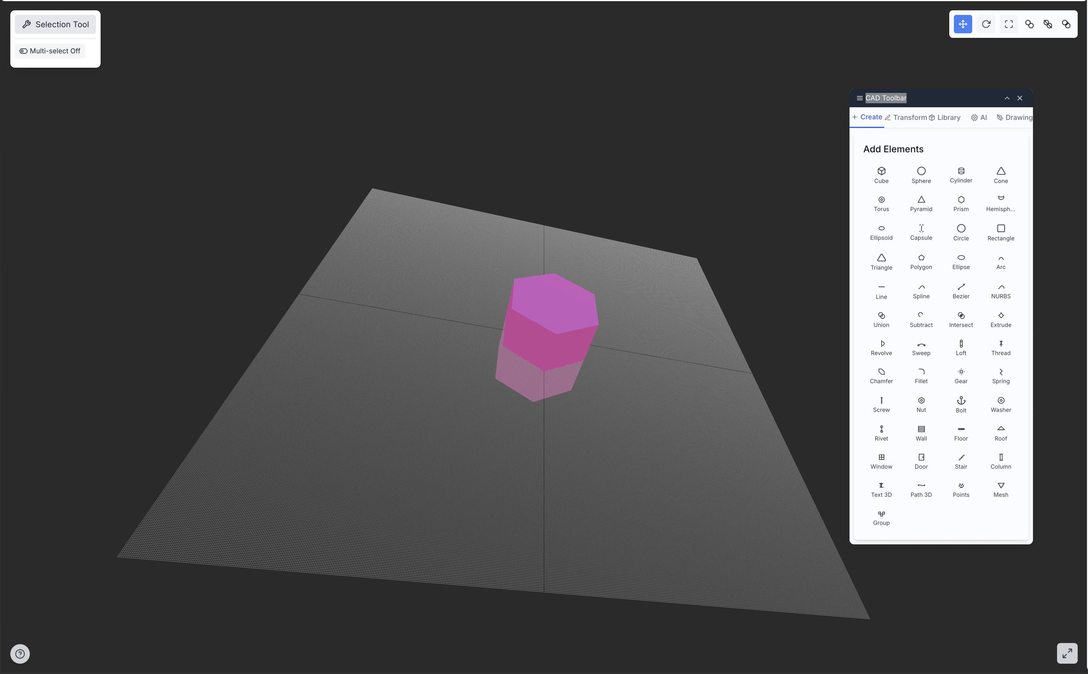
Central Working Area

- Reference Grid configurable for precision and scale
- Coordinate System with origin (0,0) at default center
- Unlimited Drawing Area with zoom and pan functions
- 2D or 3D Visualization with customizable projection options
- Visual Feedback during element creation, with:
- Real-time coordinates
- Snap indicators
- Automatic constraints (horizontal, vertical, etc.)
- Preview of elements during creation
Properties Panel (Right Sidebar)
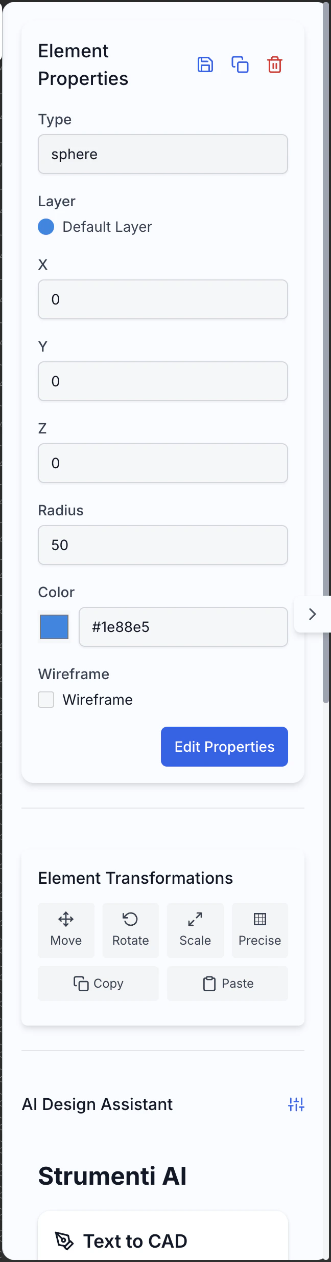
- Precise Coordinates (x, y, z) for positioning
- Dimensions (width, height, diameter, etc.) with direct modification
- Specific Properties (radius, angle, thickness, etc.) of the element
- Style (color, line thickness, transparency, material)
- Material Properties (when applicable)
- Constraints and Parameters for parametric design
Status Bar
The status bar shows contextual information:- Current Cursor Position in real-time
- Current Unit of Measure and options to change it quickly
- Status of Snap and Grid (active/inactive)
- Active Level current
- Current Visualization Scale
- Specific Help Messages for the current tool
Base Drawing Tools
The CAD Editor offers a complete series of tools for creating 2D and 3D geometries:2D Geometric Tools
Point
Line
Polyline
Rectangle
Circle
Arc
Ellipse
Spline
Polygon
Text
3D Tools
Extrusion
Revolution
Sweep
Loft
Primitive 3D
Boolean Operations
Precision Tools
For creating accurate and precise geometries, the CAD Editor offers various assistance tools:Snap to Object
Snap to Object
- Endpoint: Ends of lines, arcs, and curves
- Midpoint: Center of a line segment or arc
- Intersection: Point where two elements intersect
- Center: Center of circles, arcs, or ellipses
- Quadrant: Points on circles and ellipses
- Tangent: Points of tangency on curves
- Perpendicular: Points creating perpendicular lines
- Parallel: Points creating parallel lines
Grid and Snap to Grid
Grid and Snap to Grid
- Visible Grid: Shows a reference grid in the working area
- Snap to Grid: Forces the cursor to snap to grid points
- Adaptive Grid: Changes automatically with zoom
- Configuration: Customizes spacing, color, and style of the grid
Measurement Tools
Measurement Tools
- Distance Measurement: Between points, from point to line, between parallel elements
- Angle Measurement: Between lines, three points, or relative to axes
- Area Calculation: Calculates the area of closed shapes or regions
- Volume Calculation: Calculates the volume of 3D objects
- Curvature Analysis: Evaluates the curvature of surfaces and curves
Construction Lines and Axes
Construction Lines and Axes
- Construction Lines: Infinite lines not included in the final model
- Reference Axes: Establish orientation and position
- Reference Planes: Surface references for 3D constructions
- Temporary Guides: Appear during operations to aid alignment
Relative and Absolute Coordinates
Relative and Absolute Coordinates
- Absolute Coordinates: Relative to the system origin (0,0,0)
- Relative Coordinates: Relative to the last point or selected element
- Polar Coordinates: Using distance and angle instead of X,Y,Z
- Dynamic Input: Displaying and entering values during drawing
Geometric Constraints
Geometric Constraints
- Horizontal/Vertical: Forces lines to be perfectly horizontal or vertical
- Perpendicularity: Ensures that two lines are perpendicular at 90°
- Parallelism: Maintains parallel lines between them
- Tangency: Forces curves to be tangent
- Coincidence: Forces points to coincide
- Equality: Maintains elements with equal dimensions
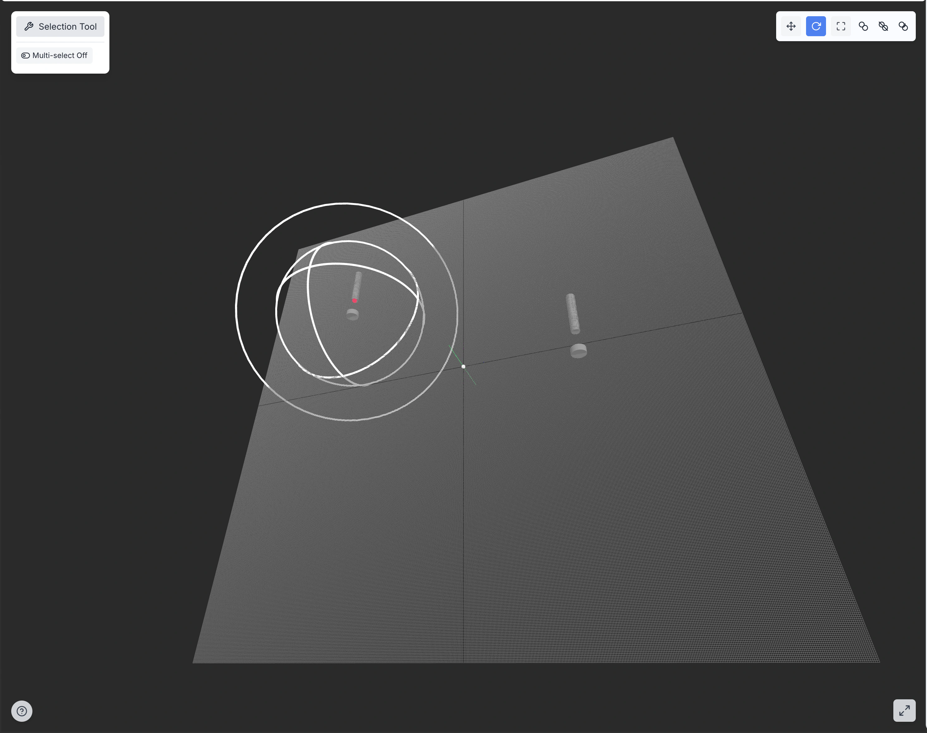
Modification and Transformation
Once you’ve created the base elements, you can modify and transform them using various tools:Selection Tools
Precise selection is crucial for effective modifications:Single Selection
Single Selection
- Select an element with a direct click
- The selected element is highlighted with the selection color
- Modification handles appear for quick adjustments
- The properties panel updates to show the parameters of the selected element
Multiple Selection
Multiple Selection
- Select multiple elements by holding Shift and clicking
- Use selection box by dragging a rectangle:
- From left to right: selects only elements completely inside the rectangle
- From right to left: selects all elements touched by the rectangle
- Use Ctrl+A to select all visible elements
- Ctrl+click on a selected element to deselect it
Selection by Properties
Selection by Properties
- Select elements based on color, level, type, or other properties
- Access this function from the Edit > Select by Properties menu
- Use complex selection queries with AND/OR operators
- Save frequently used selection queries for reuse
Selection Filters
Selection Filters
- Limits selection to specific types of objects (points, lines, faces, etc.)
- Configure filters from the status bar or contextual menu
- Quickly toggle filters with icons in the status bar
- Create custom filters for specific workflow flows
Modification Tools
After selecting elements, you can modify them using these tools:Translation
Rotation
Scaling
Mirror
Array
Fillet (Rounded Corner)
Chamfer (Miter)
Offset
Trim/Extend
Divide/Join
Advanced Transformations
For more complex modifications, the CAD Editor offers advanced transformation tools:Deformation
Deformation
- Free Deformation: Modifies shape with advanced manipulation controls at vertices
- Deformation with cage: Uses a control cage to deform complex objects
- Morphing: Gradually transforms one shape into another
- Bend: Bends objects with specified angle and radius
- Twist: Applies torsion around an axis
- Taper: Gradually narrows or widens a shape
Projection
Projection
- Projection on Plane: Projects geometries onto a reference plane
- Projection on Surface: Maps geometries onto curved surfaces
- Parallel Projection: Maintains proportions and angles
- Perspective Projection: Creates perspective effects
- Surface Development: Flattens curved surfaces for manufacturing
Alignment
Alignment
- Point-to-Point Alignment: Moves objects by making points coincide
- Axis-to-Axis Alignment: Aligns reference axes between objects
- Plane-to-Plane Alignment: Aligns reference planes between objects
- Best-Fit Alignment: Finds the best match between point sets
- Alignment with Multiple Constraints: Combines different types of alignment
Stirring
Stirring
- Stirring with Fence: Modifies parts of an object selected from a “fence”
- Stirring of Faces: Moves faces while maintaining continuity
- Proportional Stirring: Maintains proportions during stirring
- Stirring with Constraints: Respects constraints and relationships during operation
Coordinate Transformation
Coordinate Transformation
- Transformation Matrices: Applies precise mathematical transformations
- Concatenated Transformations: Combines multiple transformations in sequence
- Non-linear Transformations: Applies complex and non-linear transformations
- Transformation with Script: Uses scripts for customized transformations
Level Management
Levels allow you to organize your drawing into logical groups of elements: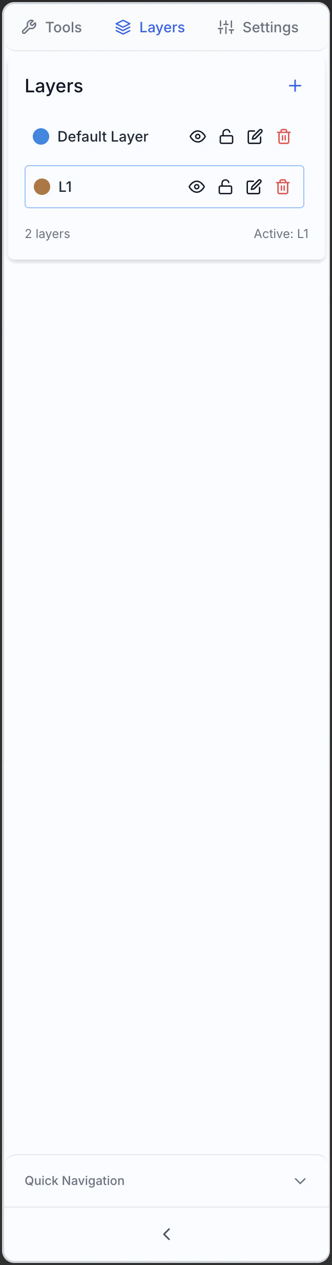
Basic Level Functionality
Level Creation
Level Creation
- New Level: Adds new levels with custom names
- Duplicate Level: Creates a copy of an existing level
- Levels from Template: Creates levels from predefined configurations
- Levels from Selection: Creates a new level from selected elements
Level Visibility
Level Visibility
- Show/Hide: Controls the visibility of each level through the eye icon
- Selective Visualization: Shows only specific levels
- Isolation: Shows a single level while hiding all others
- Visualization States: Saves and recalls visibility configurations
Active Level
Active Level
- Select Active Level: Sets the level on which new objects will be created
- Visual Indicator: The active level is highlighted in the panel
- Quick Change: Uses shortcuts or status bar selector to change level
- Automatic Activation: Option to automatically activate a level of a selected element
Level Locking
Level Locking
- Lock/Unlock: Prevents modifications to objects on locked levels
- Visible Elements: Elements on locked levels are visible but not editable
- References: Useful for using reference geometries without accidentally altering them
- Partial Locking: Options to lock only certain properties (position, dimensions, style)
Multi-Level Modification
Multi-Level Modification
- Move Between Levels: Transfers selected objects to another level
- Copy Between Levels: Duplicates objects while keeping the original on the source level
- Multi-Level Selection: Selects elements on different levels simultaneously
- Mass Modification: Modifies properties of multiple levels at once
Level Properties
Each level can have specific properties that affect the elements contained:Level Color
Level Color
- Default Color: Sets a standard color for all objects on the level
- Local Override: Individual elements can have colors that override the level’s
- ByLayer Mode: Forces elements to use the color of the level always
- ByEntity Mode: Allows individual colors for each element
Line Type
Line Type
- Default Styles: Continuous, dashed, dotted, dash-dot, etc.
- Custom Styles: Create custom line patterns
- Type Scale: Adjust the density of line pattern
- Global Application: Apply style to all elements on the level
Line Weight
Line Weight
- Default Weight: Sets the standard thickness for lines on the level
- Units: Millimeters, points, or pixels
- Scalable Display: Adapts visual thickness to display scale
- Printing: Controls how thicknesses are applied in printing
Transparency
Transparency
- Transparency Level: From completely opaque to completely transparent
- Depth Display: Controls how transparent elements interact visually
- Selection Effect: Influences the selectability of elements
- Rendering: Impact on rendering quality and speed
Level Organization
For complex projects, good level organization is essential:Level Groups
Level Groups
- Hierarchical Structure: Organize levels in groups and subgroups
- Expansion/Collapse: Show or hide internal group structure
- Inheritance: Group properties can be inherited by contained levels
- Group Operations: Apply changes to all levels in a group
Level Filters
Level Filters
- Name Filters: Find levels based on text patterns
- Property Filters: Filter by color, visibility, lock status, etc.
- Saved Filters: Create and reuse complex filter configurations
- Dynamic Filters: Automatic update based on changes
Level Templates
Level Templates
- Default Configurations: Save sets of levels as templates
- Import/Export: Share level configurations between projects
- Company Standards: Create templates conforming to your organization’s standards
- Automatic Application: Apply templates when starting new projects
Level State Management
Level State Management
- Save States: Store different visibility and property configurations
- Quick Recall: Easily switch between saved configurations
- View-linked States: Associate level configurations with specific views
- State Sequences: Create presentations or workflows
Annotation and Dimensioning
The annotation tools allow you to add technical information to your drawing:
Dimensioning Tools
Linear Dimension
Aligned Dimension
Angular Dimension
Diametral and Radial Dimension
Chain Dimension
Baseline Dimension
Dimensioning Styles
Customize the appearance of dimensions to match standards and preferences:Units and Precision
Units and Precision
- Primary Units: Millimeters, centimeters, inches, etc.
- Alternate Units: Display a second set of units (e.g. mm and inches)
- Precision: Number of decimal places to display
- Rounding: Rules for rounding values
- Formatting: Separators, leading/trailing zeros
Prefixes and Suffixes
Prefixes and Suffixes
- Prefixes: Text to add before the numeric value
- Suffixes: Text or symbols to add after the value
- Special Symbols: Ø, ², ³, °, etc.
- Tolerance Formatting: Display format for tolerances
Arrow and Extension Lines
Arrow and Extension Lines
- Arrow Style: Filled, open, dot, bar, architectural, etc.
- Arrow Size: Size of arrowhead
- Extension Lines: Length, offset, style
- Dimension Lines: Style, positioning, spacing
Text Positioning
Text Positioning
- Vertical Position: Above, centered, below the dimension line
- Horizontal Position: Centered, left, right, optimal
- Alignment: Inline with dimension or horizontal
- Rotation: Aligned or custom
Textual Annotations
Add text and notes to your drawings:Single-line Text
Single-line Text
- Quick Text: Add labels and brief notes
- Formatting: Font, size, bold, italic, underline
- Alignment: Left, center, right
- Rotation: Position text at any angle
Multi-line Text
Multi-line Text
- Advanced Editor: Create formatted paragraphs of text
- Multiple Styles: Use different styles within the same text block
- Line Spacing: Control line height, margins, indentation
- Bulleted Lists: Create formatted lists and bullet points
Text Styles
Text Styles
- Style Management: Create and save custom text styles
- Font Library: Access all system and special fonts
- Company Styles: Apply styles conforming to organizational standards
- Import Styles: Import configurations from other projects
Automatic Text Fields
Automatic Text Fields
- Date and Time: Insert current date, automatically updated
- Project Properties: Automatically insert author, title, revision
- Calculated Fields: Derived values from model properties
- Counters: Numbering for elements
Leaders
Leaders
- Reference Lines: Connect text to specific parts of the drawing
- Arrow Styles: Customize arrowheads for reference lines
- Multi-segment Lines: Create complex paths with multiple segments
- Smart Leaders: Automatically adapt to layout
Symbols and Markings
Add standardized symbols and technical markings:Standard Symbols
Standard Symbols
- Common Symbols: Welding, surface finish, tolerance grade
- Symbol Library: Access a vast collection of technical symbols
- Custom Symbols: Create and save your own symbols
- Alignment: Position symbols precisely relative to geometry
Tolerances
Tolerances
- Dimensional Tolerances: ±, upper/lower limits, fit
- Geometric Tolerances: GD&T symbols for planarity, roundness, etc.
- Control Frames: Create complete tolerance frames
- Datums: Define and reference datum points
Revision Markings
Revision Markings
- Revision Clouds: Highlight modified areas
- Revision Symbols: Indicate revision level and affected area
- Revision History: Keep track of changes
- Revision Tables: Automatically generate revision tables
Tables
Tables
- Table Creation: Add tables with rows and columns
- Styling: Customize borders, fill, and formatting
- Data Linking: Link cells to model properties
- Formulas: Use formulas to calculate values
Parametric Design
Parametric design allows you to create models that adapt automatically when dimensions or other parameters change:Parameters and Variables
Parameter Definition
Parameter Definition
- Parameter Creation: Define variables with specific names and values
- Parameter Types: Numeric, boolean, text, lists, points, vectors
- Units: Associate specific units to parameters (mm, degrees, etc.)
- Default Values: Set initial values for parameters
- Descriptions and Metadata: Document the meaning and use of each parameter
Formulas and Relations
Formulas and Relations
- Mathematical Expressions: Define mathematical relationships between parameters
- Built-in Functions: Use sin, cos, tan, sqrt, pow, min, max, etc.
- Conditional Operators: Implement if-then-else logic in formulas
- Geometry Reference: Extract values from existing geometric elements
- Custom Functions: Create and reuse complex formulas
height = width * 2 creates a relationship where height is always double the width.Parameter Tables
Parameter Tables
- Multiple Configurations: Manage different parameter configurations
- Design Variants: Quickly create alternative versions
- Import/Export: Exchange data with spreadsheets
- Parametric Testing: Test model with different value sets
- Interpolation: Generate intermediate values between configurations
Dimensional Constraints
Dimensional Constraints
- Controlled Dimensions: Link dimensions to parameters
- Bidirectional Update: Modify dimension to update parameter and vice versa
- Temporary Override: Temporarily replace parametric values
- Visibility: Show or hide parametric dimensions in drawing
- Coloring: Visually identify parametric dimensions
Geometric Constraints
Coincidence
Collinearity
Parallelism
Perpendicularity
Tangency
Symmetry
Equality
Concentricity
Fix
History-Based Modeling
Parametric modeling maintains the history of operations, allowing flexible modifications:Feature Tree
Feature Tree
- Chronological View: Shows the sequence of creation operations
- Hierarchical Organization: Displays dependencies between features
- Navigation: Expand/collapse branches and feature groups
- Search: Quickly find specific features
- Annotations: Add notes to document design decisions
Feature Editing
Feature Editing
- Direct Selection: Select a feature from the tree or model
- Parameter Update: Update values and relationships
- Geometry Edit: Change the geometric definition of the feature
- Smart Update: Model updates automatically
- Change Propagation: Changes propagate to all dependent features
Feature Reordering
Feature Reordering
- Drag and Drop: Change operation order by dragging
- Intermediate Insert: Add new features at any point in history
- Move Earlier/Later: Move features before or after others
- Dependency Analysis: View impact of reordering
- Conflict Resolution: Automatically manage dependencies during reordering
Temporary Suppression
Temporary Suppression
- Deactivation: Temporarily disable features without deleting them
- Alternative Views: Explore model versions without certain features
- Simplification: Reduce complexity to improve performance
- Diagnostics: Isolate problems by hiding specific features
- Reactivation: Restore suppressed features when needed
Component Library Management
The library allows you to reuse standard parts and components in your projects:Unified Library Usage
Access the Library
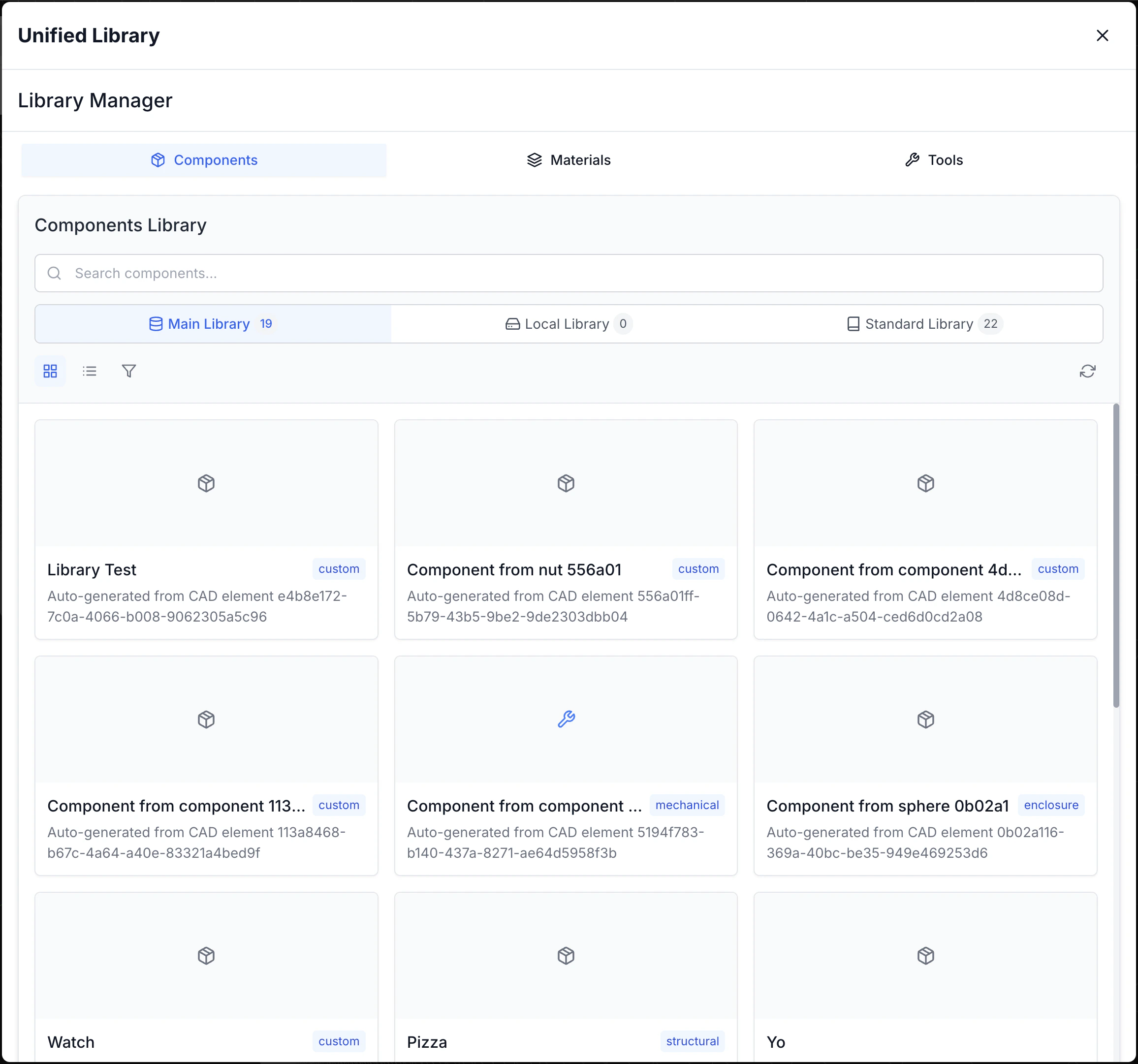
Component Insertion
Component Preview
Component Preview
- 3D Visualization: Rotate and inspect the component before insertion
- Detailed Information: Display dimensions, weight, material, and other metadata
- Variants: Explore different configurations of the same component
- Documentation: Access technical specifications and usage notes
Positioning
Positioning
- Insertion Points: Position components using predefined points
- Snap to Geometry: Align to existing elements in the drawing
- Orientation: Rotate and orient the component during insertion
- Precise Positioning: Enter exact coordinates or use constraints
- Multiple Insertion: Place multiple instances of the same component
Rotation and Scale
Rotation and Scale
- 3D Rotation: Rotate the component in any direction
- Constrained Rotation: Limit rotation to specific axes or angles
- Uniform Scale: Resize proportionally across all dimensions
- Non-uniform Scale: Modify specific dimensions while maintaining proportions of others
- Parametric Scaling: Use parameters to control dimensions
Snap Points
Snap Points
- Connection Points: Automatically align to predefined points
- Smart Snap: Recognize relationships between components (e.g. holes and screws)
- Assembly Preview: Visualize how components connect
- Automatic Constraints: Create appropriate constraints during insertion
- Manual Override: Override automatic behavior when necessary
Custom Component Creation
Save to Library
Add Metadata
- Name and description
- Tags for search
- Category and subcategory
- Author and creation date
- Version and status
Define Parameters
- Parameter names
- Default values
- Allowed ranges
- Dependencies between parameters
Parametrization
Parametric components can adapt to various needs:Variable Dimensions
Variable Dimensions
- Dimensional Parameters: Control length, width, height, diameters
- Allowed Ranges: Define min/max limits for each parameter
- Standard Dimensions: Create lists of standard values (e.g. normalized diameters)
- Predefined Scales: Configure common scale ratios
- Sizing Rules: Define how dimensions interact with each other
Configurations
Configurations
- Default Configurations: Create saved sets of parameters
- Product Variants: Define standard component versions
- Configuration Tables: Manage series of components with parametric tables
- Fly Configuration: Modify parameters during insertion
- Context-dependent Configuration: Adapt automatically to insertion context
Conditional Features
Conditional Features
- Optional Features: Enable/disable specific functionalities
- Conditional Logic: Define rules based on parameter values
- Alternative Geometry: Change shape based on specific conditions
- Intelligent Suppression: Automatically hide irrelevant details
- Context-adaptive Behavior: Modify behavior based on assembly context
Derived Properties
Derived Properties
- Automatic Calculations: Generate properties like weight, volume, center of mass
- Physical Properties: Estimate characteristics like moment of inertia, resistance
- Estimated Costs: Calculate costs based on material, complexity, operations
- Performance Estimates: Estimate performance parameters (e.g. flow rate, thermal resistance)
- Compatibility: Verify compatibility with other components
AI Design Assistant Integration
The AI Design Assistant helps you create complex geometries from textual descriptions: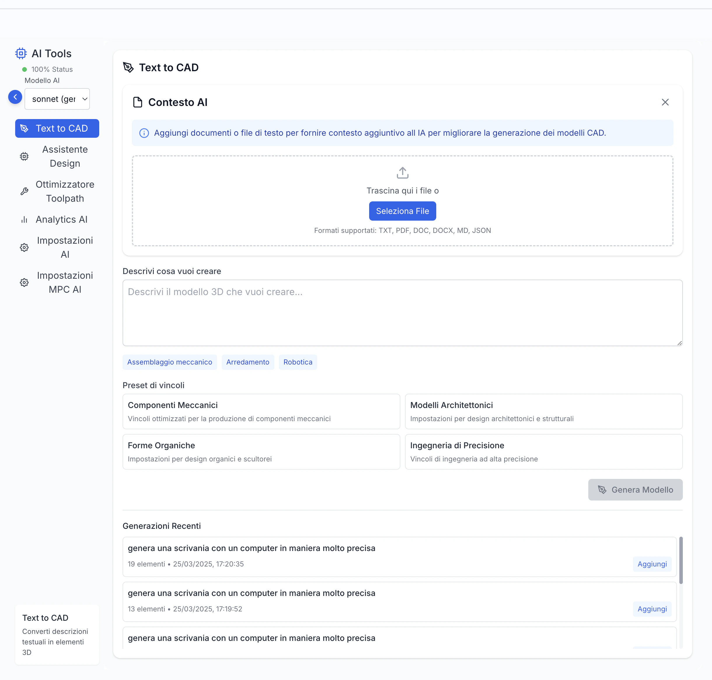
Using the AI Design Assistant
Access the Assistant
Enter Description
Types of Generatable Models
The AI Design Assistant can generate various categories of models:Organic Shapes
Mechanical Components
Patterns and Textures
Geometric Complexes
Effective AI Prompts
To get the best results from the AI Design Assistant, follow these guidelines:Be Specific
Be Specific
Use Technical Terminology
Use Technical Terminology
Specify Constraints
Specify Constraints
Describe the Function
Describe the Function
Gradual Iteration
Gradual Iteration
- “Create a gear with 40 teeth, module 2, 10mm thickness”
- “Now add a second 10-tooth gear meshing with the first”
- “Add shafts for both gears with appropriate diameter”
- “Add a frame that contains both gears maintaining correct center distance”
Modifying AI Results
After generation, you can refine the model:Manual Editing
Manual Editing
- Standard Tools: Use normal CAD tools to refine geometry
- Direct Edit: Manipulate faces, edges, and vertices of the generated model
- Boolean Operations: Combine with other shapes to achieve more complex geometries
- Additional Features: Add holes, threads, chamfers, fillets, and other features
- Topology Optimization: Lighten and optimize structure while maintaining strength
Parameterization
Parameterization
- Parameter Identification: Convert fixed dimensions to modifiable parameters
- Relationship Creation: Define mathematical relationships between parameters
- Configuration Tables: Create model variants with different configurations
- Parametric Testing: Verify model behavior with different parameter combinations
- Documentation: Add explanatory notes for created parameters
Combination
Combination
- Model Merging: Combine multiple AI results into a single complex model
- Component Library: Save generated parts for reuse in future projects
- Mix Techniques: Integrate AI models with manually created or library components
- Assembly: Use generated models as components in a larger assembly
- Variants: Create alternative versions based on the same initial concept
Optimization
Optimization
- Geometry Simplification: Reduce complexity for better performance
- Manufacturing Optimization: Modify to suit specific production processes
- Structural Analysis: Verify and reinforce critical areas
- Weight Reduction: Lighten the model while maintaining necessary strength
- Standardization: Adapt dimensions and features to industry standards
File and Project Management
The CAD Editor offers complete functionality for managing your projects:Saving and Opening Files
Native Formats
Native Formats
- Proprietary Format: Save in .cad or .model format to maintain all information
- Complete Projects: Save entire projects with all components and relationships
- Complete Metadata: Preserve parameters, history, constraints, and annotations
- Compression: Optimize file sizes for efficient storage
- Protection: Options to protect files with password or encryption
Autosave
Autosave
- Periodic Saving: Recover work in case of unexpected closure
- Configurable Interval: Set autosave frequency
- Separate Location: Autosave files don’t overwrite originals
- Automatic Recovery: Offers to recover interrupted sessions at startup
- Automatic Cleanup: Manages obsolete autosave files
Backup
Backup
- Incremental Backups: Automatically create backup copies at configurable intervals
- Backup Rotation: Maintains a specific number of previous versions
- Cloud Backup: Option to save backups in cloud for greater security
- Local Backups: Storage on local devices or folders
- Easy Recovery: Simple interface for recovering from backups
Version History
Version History
- Integrated Versioning: Track significant changes over time
- Version Annotations: Add notes to describe changes
- Visual Comparison: View differences between versions
- Selective Recovery: Recover specific elements from previous versions
- Project Timeline: View project evolution over time
Import and Export
Standard CAD Formats
Standard CAD Formats
- 2D Formats: DXF, DWG for technical drawings
- 3D Formats: STEP, IGES, SAT for solid models
- Neutral Formats: X_T, X_B for exchange between different CAD systems
- Import Options: Control over layers, units, tolerances
- Automatic Repair: Correction of common issues during import
Exchange Formats
Exchange Formats
- Intermediate Formats: Conversion between different CAD/CAM systems
- Data Preservation: Options to maintain specific information
- Mapping: Smart conversion between different data structures
- Validation: Verify data integrity during conversion
- Reports: Documentation of any issues or data loss
Mesh Formats
Mesh Formats
- STL: Standard for 3D printing and rapid prototyping
- OBJ: Common format for 3D graphics
- PLY: Polygon format for 3D scans
- 3MF: Modern format for additive manufacturing
- Resolution Options: Control over mesh density
Raster Images
Raster Images
- PNG/JPG: Export images for documentation
- Configurable Resolution: Control over image quality
- Transparency: Support for transparent backgrounds (PNG)
- Current or Multiple Views: Export current view or multiple views
- Watermark: Option to add watermarks to images
PDF
- Vector Documentation: Export to PDF format for sharing
- 3D PDF: Include interactive 3D models in PDFs
- Layout Configuration: Control over page size and scale
- PDF Layers: Maintain layer structure in export
- Metadata: Include project and author information
Managing Multiple Drawings
Referenced Drawings
Referenced Drawings
- External References: Create links between different drawings
- Dependencies: View and manage relationships between files
- Relative References: Maintain links even when changing path
- Change Notifications: Alerts when referenced files are modified
- Selective Loading: Load only necessary references for better performance
Automatic Update
Automatic Update
- Synchronization: Automatically update drawings when references change
- Change Propagation: Transfer changes between linked drawings
- Update Control: Options for manual or automatic updates
- Local Overrides: Maintain local modifications during updates
- Conflict Resolution: Tools for managing conflicting changes
Multiple Layouts
Multiple Layouts
- Different Views: Create different views and configurations of the same model
- Technical Sheets: Generate multiple views, sections, and details in a single document
- Layout Templates: Use standardized formats for technical documentation
- Custom Configurations: Adapt layouts to specific documentation needs
- Multiple Printing: Manage different settings for each layout
Worksheets
Worksheets
- Organization: Group related drawings in a single project
- Easy Navigation: Quickly switch between related drawings
- Consistency: Maintain consistency between drawings in the same project
- Share Configurations: Use same styles and standards across drawings
- Batch Processing: Apply operations to groups of related drawings
Cloud and Collaboration
Cloud Synchronization
Cloud Synchronization
- Cross-platform Access: Access your projects from any device
- Automatic Backup: Safeguard your work with cloud backups
- Versioning: Track and manage project versions
- Selective Sync: Choose which projects to sync locally
- Offline Work: Continue working without connection and sync later
Sharing
Sharing
Access Control
Access Control
- Granular Permissions: Manage who can view, comment, or modify
- User Groups: Assign permissions to teams or departments
- Temporary Access: Grant time-limited access
- Watermark: Add watermarks to shared files for security
- Revoke Access: Remove permissions when no longer needed
Comments and Annotations
Comments and Annotations
- Contextual Notes: Add comments directly on drawing elements
- Discussion Threads: Organized conversations about specific aspects
- Assignments: Assign comments or requests to specific members
- Notifications: Alerts when new comments are added
- Resolution: Mark issues as resolved after addressing them
Tips and Best Practices for the CAD Editor
Workflow Optimization
Keyboard Shortcuts
Keyboard Shortcuts
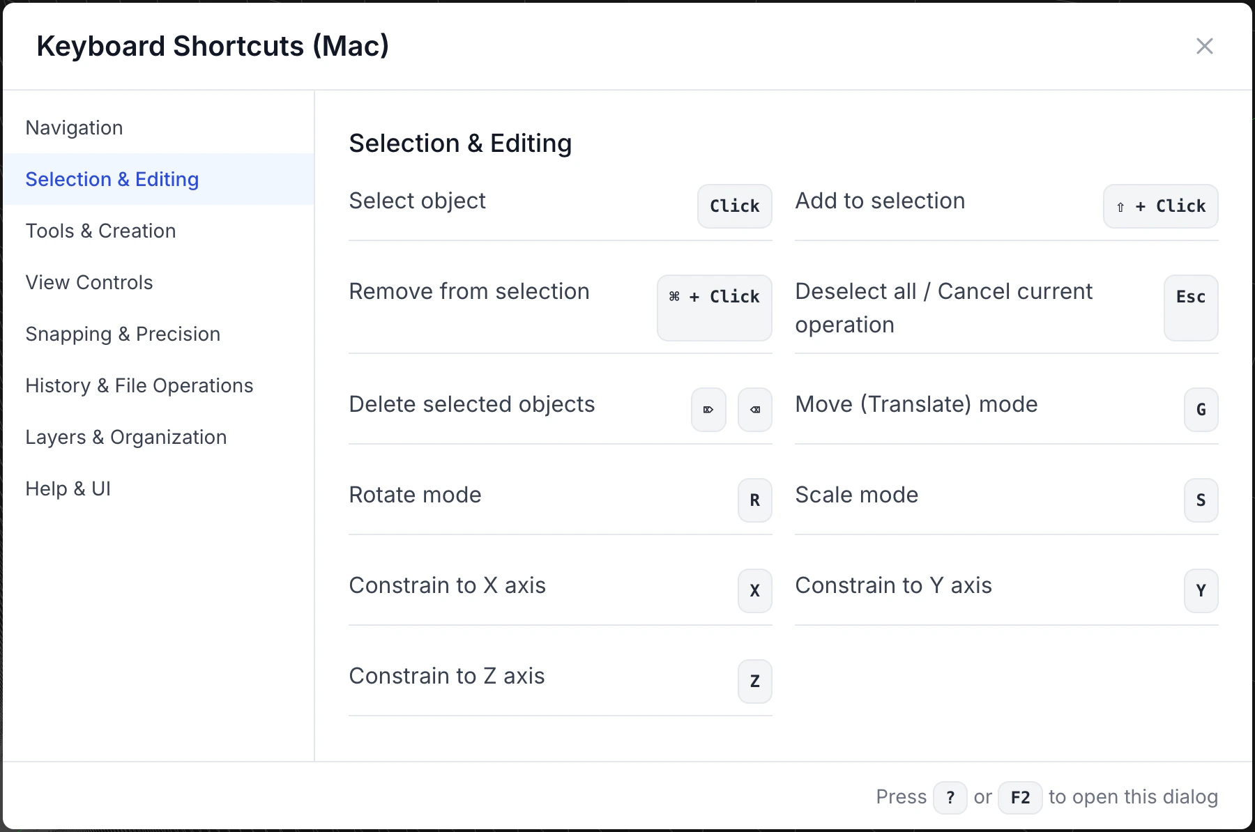
- Ctrl+S (Cmd+S): Save
- Ctrl+Z/Y (Cmd+Z/Shift+Cmd+Z): Undo/Redo
- Ctrl+C/V/X (Cmd+C/V/X): Copy/Paste/Cut
- Space: Toggle between current tool and selection
- F: Fit to view
- Ctrl+1/2/3/4 (Cmd+1/2/3/4): Standard views (Front/Top/Right/Isometric)
- Ctrl+B (Cmd+B): Regenerate model
- Tab: Cycle through selectable elements under cursor
- Delete: Delete selected elements
Interface Customization
Interface Customization
- Workspace Layout: Configure panel arrangement and sizes
- Custom Toolbars: Add frequently used tools
- Menus and Palettes: Organize tools in logical groups
- Color Themes: Choose themes optimized for long work sessions
- User Profiles: Save different configurations for different types of activities
Templates
Templates
- Basic Templates: For standard projects with default settings
- Industry Templates: Optimized for specific disciplines (mechanical, architectural, etc.)
- Company Templates: With your organization’s standards, blocks, and styles
- Personal Templates: Adapted to your specific workflow
- Template Library: Manage and share templates within the team
Frequent Saving
Frequent Saving
- Incremental Saves: Create numbered versions to track evolution
- Autosave Configuration: Set short intervals (5-10 minutes)
- Save Before Complex Operations: Create safe restore points
- Regular Backups: Export safety copies to external devices
- Save Comments: Add notes about what was modified
Organizing Models
Naming Conventions
Naming Conventions
- Prefixes for type: Use prefixes like “ASM_” for assemblies, “PRT_” for parts
- Logical Naming: Include part numbers or project codes
- Versioning: Incorporate version numbers or dates
- Brief Descriptions: Balance brevity and clarity
- Consistency: Follow the same system across all projects
Hierarchical Structure
Hierarchical Structure
- Functional Components: Group by function or system
- Intermediate Assemblies: Create for related parts
- References: Use parent-child relationships correctly
- Visibility Management: Organize for easy selective viewing
- Modularity: Design for reuse and maintainability
Metadata
Metadata
- Standard Properties: Author, date, status, revision
- Keywords and Categories: Keywords for easy search
- Technical Information: Material, production process, tolerances
- Usage Notes: Special instructions or limitations
- External References: Links to specific or related documentation
Integrated Documentation
Integrated Documentation
- Project Notes: Explanations of design decisions
- Change Log: Main changes over time
- Project Constraints: Documentation of project criteria
- Instructions: How to use or modify the model
- External References: Links to specific or applicable standards
Performance Optimization
Simplifying Geometry
Simplifying Geometry
- Appropriate Detail: Use only the necessary level of detail
- Feature Suppression: Temporarily disable unnecessary details
- Simplified Representations: Create lightweight versions for assemblies
- Derived Parts: Use simplified models for reference
- Schematic Substitution: Replace complex components with schematic representations
Managing Levels
Managing Levels
- Detail Levels: Organize elements by importance
- Level Freezing: Make inactive levels unmodifiable
- Construction Geometry: Separate auxiliary geometry
- Visibility Overrides: Configure presets for different activities
- Cleaning: Periodically remove empty or unused levels
Selective Visualization
Selective Visualization
- Wireframe: For quick navigation and selection
- Shaded Simple: For general editing
- Realistic Rendering: Only when necessary for evaluations
- Environmental Occlusion: Balancing speed and comprehensibility
- Adaptive Visualization: Automatic adjustment based on actions
Memory Management
Memory Management
- Open File Limitation: Keep only necessary files open
- Cache Cleaning: Regularly clear temporary cache
- Database Optimization: Periodically compact databases
- Resource Monitoring: Keep an eye on memory usage
- Regular Restart: Restart application during long breaks
With these features and tools, the CAD Editor offers everything you need to create and manage complex 2D and 3D models. In the next section, we’ll explore the CAM Editor and its toolpath generation capabilities.