Documentation Index
Fetch the complete documentation index at: https://docs.cadcamfun.xyz/llms.txt
Use this file to discover all available pages before exploring further.
CAM Editor
The CAM Editor is a fundamental component of the application that allows you to transform your CAD models into toolpaths and G-code for CNC machining. This section explores in detail all the features available in the CAM Editor.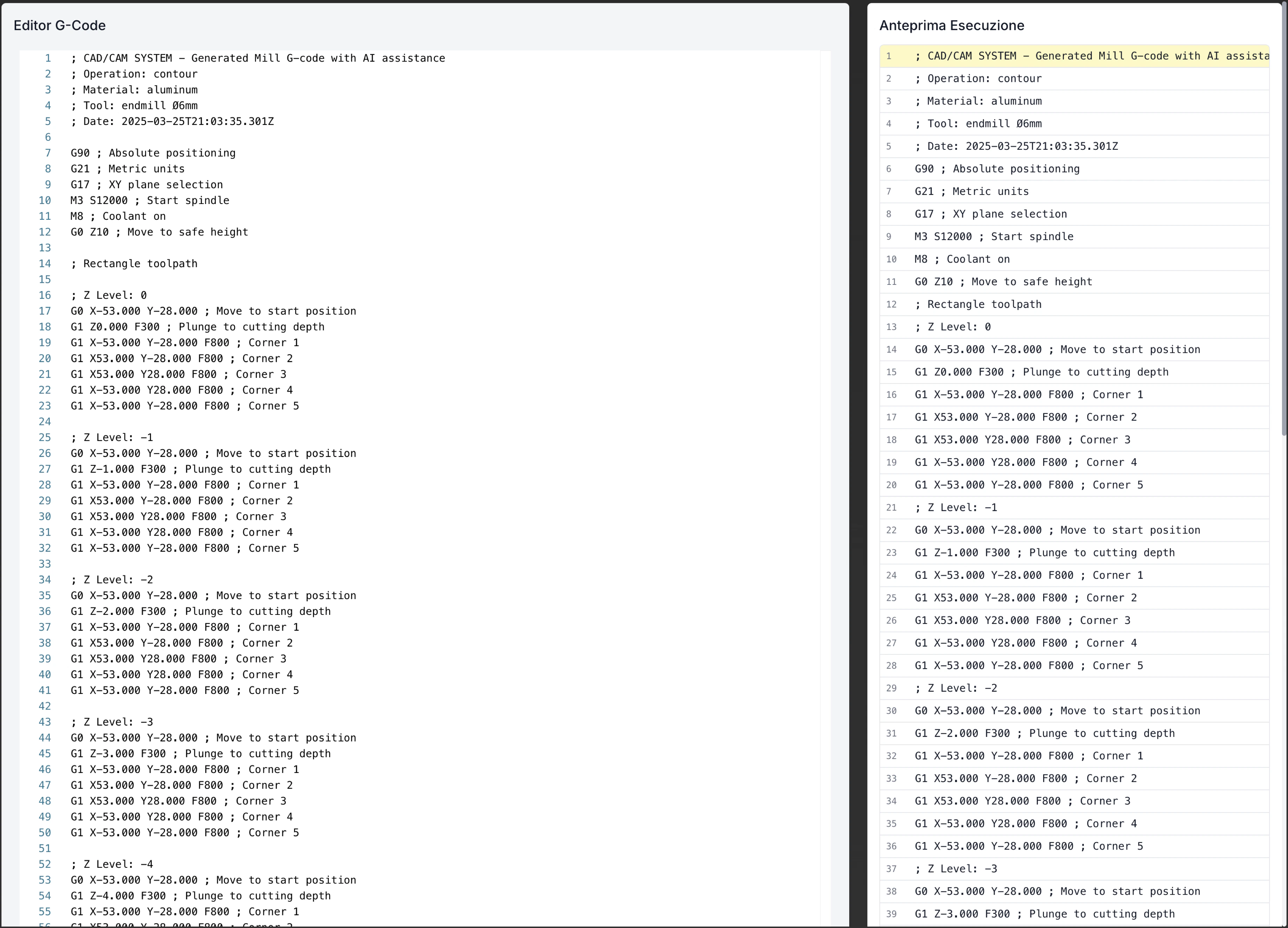
CAM Editor Interface
The CAM Editor presents a comprehensive interface organized to facilitate workflow from design to production:Top Toolbar

File Menu
File Menu
Simulation Menu
Simulation Menu
View
View
- Display Styles: Modify how models and toolpaths are displayed
- Standard Views: Front, side, top, isometric
- Transparency: Control transparency to view internal elements
- Sections: Create section views to analyze internal details
- Measurements: Tools to measure distances and angles
- Display Filters: Show/hide specific operation types
Library Button
Library Button
Main Tabs
Main Tabs
- Preview: View model and toolpaths
- G-code Editor: View and edit generated G-code
- Toolpath Viewer: Detailed analysis of toolpaths
- Post-processor: Configuration and generation of specific G-code
- Documentation: Creation of workshop documentation
Left Sidebar
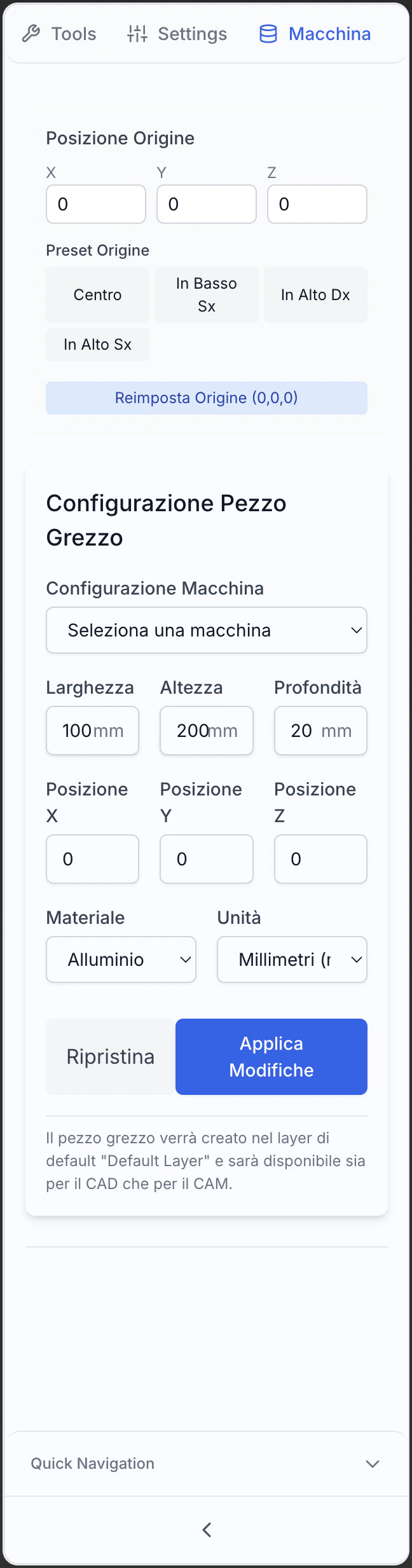
- Machine
- Levels
- Settings
Machine Types
Machine Types
- Milling Machine: 3, 4, 5 axis, vertical or horizontal
- Lathe: Standard, multi-spindle, with motorized tools
- Combined Machine: Turning and milling
- Wire EDM: Wire or submerged arc
- Laser/Plasma/Waterjet: For 2D machining
- Workpiece Setup: Advanced multi-process setup
Machine Parameters
Machine Parameters
- Axis Travel: Limits of movement in each direction
- Speeds and accelerations: Limits of speed and acceleration
- Tool Change: Position and process of tool change
- Home and origins: Reference positions
- Compensations: Tool offset and workpiece
- Cooling Systems: Type and coolant control
Physical Limitations and Capabilities
Physical Limitations and Capabilities
- Physical Limits: Maximum size of workpiece
- Spindle Power: Power capacity and torque
- Accuracy: Tolerances and repeatability
- Special Features: Advanced options available
- Measurement Systems: Available input devices
- Protections: Safety zones and controls
Central Display Area
- Preview
- G-code Editor
- Toolpath Viewer
- Post-processor
- 3D Model: Visualization of the workpiece to be machined
- Rough: Representation of the starting material
- Toolpaths: Visualization of the generated trajectories
- Rapid Moves: Outside moves outside the material (typically in different color)
- Tool Positions: Entry, exit, and change direction points
- Spindle Removal Simulation: Visualization of material removal progress
Right Panel (Control)
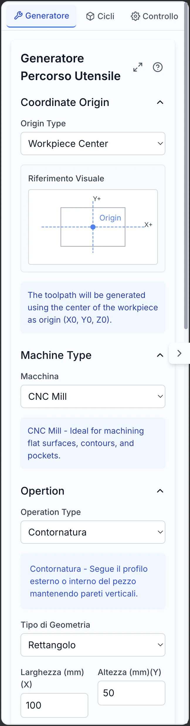
- Generator
- Cycles
- Control
Operation Selection
Operation Selection
- Contouring: Machining along external or internal profiles
- Trough: Internal area emptying
- Drilling: Creation of holes with various cycles
- Flattening: Machining of flat surfaces
- 3D Machining: Strategies for complex surfaces
- Combined Operations: Multiphase custom machining
Machining Parameters
Machining Parameters
- Depth: Total and incremental value
- Feed: Speed of movement in the material
- Spindle Speed: RPM or cutting speed
- Over-travel: Material left for subsequent operations
- Coolant: Control of the cooling system
- Operation Sequence: Sequence of machining
Cutting Strategies
Cutting Strategies
- Zigzag: Forward and backward movements
- Spiral: Movements in a spiral from inside to outside or vice versa
- Parallel: Parallel passes in one direction
- Radial: Moves from center to outside or vice versa
- Morphing: Transition between different strategies
- Adaptive: Automatic optimization of the path
Bottom Status Bar
The status bar shows contextual information:- Current position in the active coordinate system
- Current unit of measurement with quick change option
- Simulation State (inactive, running, paused)
- Information about the selected toolpath (length, estimated time)
- System messages and warnings about ongoing operations
- Progress of path generation during complex operation calculations
Importing and Preparing Models
Before generating toolpaths, it’s necessary to import and prepare the CAD models correctly:Importing Models
From Internal CAD Editor
From Internal CAD Editor
- Direct Transition: Go directly from CAD model to CAM programming
- Preservation of Parameters: Maintains parametric relationships and model history
- Bidirectional Updates: CAD changes automatically reflect in CAM
- Feature Recognition: Automatic recognition of workpiece features
- Selective Import: Import only specific parts of the model
From File
From File
- Supported Formats: Import from STEP, IGES, STL, X_T, Parasolid, etc.
- Import Options: Scale control, unit conversion, tolerance checks
- Automatic Repair: Correction of common issues in models
- Simplification: Options to reduce complexity if necessary
- Mesh-to-B-rep Conversion: Conversion of mesh to solid models
Reference Geometry
Reference Geometry
- Morse and Fixtures: Import systems for simulation
- Machine Components: Elements of the machine for collision checking
- Supports and Positioners: Support elements for the workpiece
- Reference Coordinates: Coordinate systems and reference points
- Control Volumes: Areas to avoid during machining
Preparing the Model
Aligning the Workpiece
- Use rotations and translations to position correctly
- Align with the machine’s coordinate system
- Consider the accessibility of tools
- Optimize for reducing setup changes
Defining the Rough Stock
- Standard shapes (block, cylinder) or custom
- Dimensions with appropriate overtravel
- Selection of material from the library
- Relative positioning to the finished model
Setting the Origin
- Typically on a corner or center of the workpiece
- Consider easily identifiable points on the machine
- Define one or more coordinate systems (WCS)
- Align with the model’s characteristics
Selecting Geometries
- Automatic recognition of holes, troughs, profiles
- Manual selection of surfaces or features
- Organization by type of machining
- Definition of priorities and sequences
Defining the Setup
Coordinate Systems
Coordinate Systems
- WCS Setup: Definition of the working coordinate system
- Multiple Origins: Configuration of multiple systems for complex operations
- Alignment with Features: Orientation based on geometry
- Plane Rotations: Definition of non-standard workplane rotations
- Origins for Different Operations: Dedicated zeros for specific operations
Reference Points
Reference Points
- Tappable Points: Definition of easily measurable points
- Edges and Faces: Geometric references for setup
- Registrations and Pins: Precise alignment points
- Centering Marks: Quick alignment marks
- Base Plate: Definition of base for support
Machine Alignment
Machine Alignment
- Axis Mapping: Mapping of machine axes
- Table Rotations: Configuration of rotary axes
- Multi-axis: Setup for 4 or 5 axis machining
- Dynamic Transformations: TCPC setup for 5 axes
- Machine Kinematics: Definition of axis movements
Workpiece Clamping
Workpiece Clamping
- Clamping Systems: Definition of clamps, bushings, or clamps
- Supports and Supports: Support elements for the workpiece
- Blocking Areas: Dedicated areas for securing
- Tool Accessibility: Checking tool access with constraints
- Collisions: Checking interference between tools and clamping systems
Managing Tools and Materials
Proper management of tools and materials is crucial for effective machining operations:Tool Library

Types of Tools
Types of Tools
- End Mills: Candela, sphere, toroid, conical, etc.
- Spindles: Helical, cannon, for centers, for deep holes
- Thread Mills: For internal and external threads
- Turning Tools: For roughing, finishing, channeling, threading
- Special Tools: Cutters, tools for wire erosion, creators
- Boring and Threading Tools: For precision hole finishing and thread creation
Tool Parameters
Tool Parameters
- Geometric: Diameter, length, tip radius, angles
- Constructive: Material, coating, number of cutting edges
- Operational: Recommended speeds and feeds, cutting depths
- Identifying: Tool number, code, manufacturer, stock position
- Mounting: Toolholders, overhang lengths, adapters
- Wear: Parameters for tool monitoring and tool life
Tool Geometry
Tool Geometry
- 2D Profiles: Simplified representation for quick simulations
- 3D Models: Accurate representation for collision checking
- Complete Assembly: Modeling of the entire tool-toolholder assembly
- Customization: Custom tool geometry for non-standard applications
- Import: Support for tool catalogs from manufacturers
- Parameterization: Creation of parametric tool families
Creating Custom Tools
Creating Custom Tools
- Tool Interface: Dedicated interface for defining geometries
- Parameterization: Creation of tools from base parameters
- Import from CAD: Use of 3D models created in CAD
- Derivation: Modification of existing tools
- Validation: Checking consistency and completeness of parameters
- Documentation: Adding notes and technical specifications
Material Management
Material Database
Material Database
- Standard Categories: Steels, aluminum, titanium, plastics, wood, etc.
- Specific Alloys: Cataloged by commercial name and standard
- Grades and Treatments: Differentiation by material state
- Filtered Search: Find materials by specific properties
- Certified Materials: Data verified by manufacturers
- Import Catalogs: Support for external databases
Material Properties
Material Properties
- Physical Properties: Density, thermal conductivity
- Mechanical Properties: Hardness, resistance, ductility
- Machinability: Indicators of machinability for various processes
- Limitations: Maximum temperatures, susceptibility to damage
- Compatibility: Interactions with coolants and coatings
- Sustainability: Information on recyclability and environmental impact
Custom Materials
Custom Materials
- Zero Creation: Complete definition of new materials
- Cloning and Modification: Starting from similar materials
- Data Import: From technical drawings and external databases
- Testing and Validation: Verification through tests
- Documentation: Adding notes and references
- Sharing: Distribution within the team or organization
Cutting Parameters
Cutting Speed
Cutting Speed
- Cutting Speed (Vc): Measured in m/min or ft/min
- Spindle Speed (n): RPM calculated based on tool diameter
- Machine Limits: Adjustment to machine speed limits
- Considerations on Material: Optimal speeds for various materials
- Corrective Factors: Adjustments for specific conditions
- Optimization Strategies: Variation of speed for different phases
Feed Rate
Feed Rate
- Feed per Tooth (fz): Measured in mm/tooth or in/tooth
- Feed per Revolution (fn): Full feed for each rotation
- Linear Feed (f): Speed of movement in mm/min or in/min
- Adaptation to Conditions: Variation based on depth, entry, etc.
- Tool Limitations: Respects tool capacity
- Considerations on Finishing: Balancing between speed and quality
Depth of Cut
Depth of Cut
- Axial Depth (ap): Cutting depth in the direction of the tool axis
- Radial Depth (ae): Cutting width perpendicular to the axis
- Width/Depth Ratio: Optimal proportion for various tools
- Multiple Passes: Dividing deep cuts into incremental passes
- Dynamic Adjustment: Adjustment based on cutting conditions
- Finishing Passes: Reduced depths for better precision
Coolant
Coolant
- Coolant Types: Emulsion, full oil, compressed air, cryogenic
- Pressure and Flow: Settings for volume and pressure
- Application Strategy: Continuous, pulsed, targeted
- Specific Conditions: For deep drilling, difficult materials, etc.
- Chip Removal: Efficient chip management
- Environmental Considerations: Eco-compatible options
Automatic Optimization
Automatic Optimization
- Technology Database: Optimal parameters based on historical data
- AI Algorithms: Intelligent suggestions based on learning
- Feedback from Previous Operations: Adaptation based on historical results
- Goal Balancing: Optimization for speed, quality, or tool life
- Context Adaptation: Consideration of all relevant variables
- Continuous Update: Constant improvement of recommendations
Toolpath Generation
The CAM Editor offers various strategies for generating optimized toolpaths:Milling Operations
Contouring/Profiling
- Cutting external or internal profiles
- Machining pockets with islands
- Perimeter finishing operations
- Zigzag or spiral patterns
- Optimization to minimize tool load
- Automatic management of islands and obstacles
Face Milling
- Parallel passes with optimal overlap
- Management of multiple areas on the same plane
- Optimization of connecting movements
Ramp/Helix
- Linear ramp entry for grooves
- Helical movement for pockets and holes
- Entry angle control
Scanline
- Optimizable parallel directions
- Overlap control for uniform finish
- Efficient management of flat and curved areas
3D Machining
- Constant Z machining for steep walls
- Radial finishing for conical surfaces
- Pencil machining for corners and fillets
High-Speed Machining
- Constant radial engagement control
- Avoids sharp direction changes
- Maintains constant tool loads
Drilling Operations
Simple Drilling
- Control of depth and overtravel
- Options for quick drilling in simple materials
- Management of hole families with same characteristics
Thread Milling
- Support for rigid tapping or with compensation
- Automatic calculation of parameters based on pitch
- Options for rotation reversal or special cycles
Boring
- Advanced control of speed and feed rate
- Management of controlled entry and exit
- Options for tool orientation during exit
Reaming
- Operations for greater dimensional precision
- Control over surface finish
- Options for non-concentric machining
Drilling Cycles
- Deep drilling with complete or partial retractions
- Chip breaking cycles for deep holes
- Advanced control of incremental depth
Turning Operations
Roughing
- Cutting pattern parallel to axis or profile
- Control of chip thickness
- Management of uniform overtravel for finishing
Finishing
- Advanced feed control
- Optimization for surface quality
- Management of fillets and details
Threading
- Support for various standards (metric, imperial, etc.)
- Entry and exit strategies
- Multi-pass cycles for deep threads
Grooving
- Cycles for simple or profiled grooves
- Control of width and depth
- Strategies for chip evacuation
Parting
- Control of feed rate
- Management of separation
- Options for piece support
Special Operations
Engraving
Engraving
- Text and Symbols: Engraving of characters and logos
- Depth Control: Variation for 3D effects
- Optimized Paths: Minimization of rapid movements
- Fonts and Styles: Support for various text styles
- Precision Control: Adaptation to different sizes
- Specific Strategies: For difficult or delicate materials
4/5 Axis Machining
4/5 Axis Machining
- Multi-face Machining: Single setup for multiple sides
- Tool Tilt: Optimization of angle for better results
- Wrapping Paths: Follow geometry continuously
- Synchronized Rotations: Smooth movements of all axes
- Advanced Strategies: Machining of blades, propellers, organic shapes
- Collision Control: Automatic interference prevention
Wire/EDM
Wire/EDM
- Wire Cutting: 2D and 4-axis paths for wire EDM
- Plunge EDM: Strategies for plunge EDM
- Taper Control: For inclined cuts
- Multi-pass: Roughing and finishing strategies
- Wire Compensation: Adaptation to wire diameter
- Management of Notches and Corners: Specific techniques for details
Laser/Plasma/Waterjet
Laser/Plasma/Waterjet
- Path Optimization: Reduction of cutting times
- Lead-in/Lead-out Management: Optimized entry and exit
- Nesting: Efficient arrangement of multiple parts
- Quality Control: Parameter adjustment for precise edges
- Material Management: Adaptation to different thicknesses and types
- Waste Minimization: Optimization of material usage
Path Optimization
Minimizing Rapid Movements
Minimizing Rapid Movements
- Optimal Path Calculation: Algorithms to minimize distances
- Operation Grouping: Completion of similar operations
- Intelligent Links: Choice of most efficient path
- Automatic Ordering: Operation sequence to reduce movements
- Adaptive Safety Heights: Variation based on obstacles
- Multi-tool Optimization: Reduction of tool changes
Optimized Entries and Exits
Optimized Entries and Exits
- Ramp or Helical Entries: Reduction of initial stress
- Tangential Exits: Prevention of marks on the piece
- Controlled Approach: Management of approach speed
- Overlap Strategies: Eliminate entry/exit marks
- Context Adaptation: Different strategies for different situations
- Mark Minimization: Techniques to reduce visibility of entry/exit
Corner Control
Corner Control
- Corner Rounding: Smooths direction changes
- Adaptive Speed: Automatic reduction at corners
- Arc Insertion: Replaces sharp angles with fillet arcs
- Movement Division: Breakdown of complex movements
- Acceleration Control: Advanced management of accelerations
- Curve Anticipation: Early preparation for direction changes
Pass Overlap
Pass Overlap
- Optimal Percentage: Balance between efficiency and quality
- Adaptive Variation: Adaptation to different geometries
- Residual Ridge Control: Minimization of marks between passes
- Final Pass Techniques: Uniform removal of residual material
- Alternating Patterns: Direction alternation for better finish
- Diameter Compensation: Adaptation to effective tool diameter
Simulation and Verification
Before sending the G-code to the CNC machine, it’s essential to simulate and verify the operations:
Toolpath Simulation
3D Visualization
3D Visualization
- Complete Tool Model: Visualization of the entire assembly
- Color Coding: Visual identification of different operations
- Speed Indicators: Color variation based on speed
- Selective Display: Filtering of operations to display
- Model Overlay: Comparison with final model
- Wireframe/Shaded Mode: Different display options
Collision Detection
Collision Detection
- Automatic Verification: Identification of interferences
- Collision Analysis: Between tool, holder, workpiece, fixtures
- Interference Display: Highlighting of problem areas
- Real-time Alerts: Notifications during simulation
- Safety Heights: Verification of minimum distances
- Collision Report: Documentation of potential problems
Step-by-Step Simulation
Step-by-Step Simulation
- Movement Control: Analysis of each single movement
- Block Navigation: Moving between specific G-code blocks
- Critical Points: Identification of problem areas
- Automatic Zoom: Focus on active area
- Real-time Data: Display of current parameters
- Original Comparison: Continuous verification with target model
Real-time Simulation
Real-time Simulation
- Realistic Time: Movement at programmed speed
- Accelerations: Simulation of machine accelerations
- Tool Change: Realistic timing for changes
- Speed Control: Ability to speed up or slow down
- Programmed Stop: Pause at points of interest
- Real-time Statistics: Continuous update of data
Material Removal Simulation
Material Removal Simulation
- Volumetric Model: 3D representation of stock
- Progressive Removal: Real-time material removal
- Result Display: Final model after all operations
- Residual Material: Highlighting of unremoved material
- Sections: Analysis of internal geometry
- Target Comparison: Verify differences with target model
Machining Analysis
Machining Times
Machining Times
- Total Time: Estimate of total machining time
- Operation Times: Breakdown for each operation
- Tool Time: Analysis of usage time per tool
- Rapid vs. Machining: Distinction between productive and non-productive times
- Tool Change: Time dedicated to tool changes
- Optimization: Suggestions for reducing times
Residual Material
Residual Material
- Color Map: Graphical visualization of residual material
- Quantitative Analysis: Calculation of residual volume
- Critical Areas: Where too much or too little material remains
- Tolerance Comparison: Verification against requirements
- Operation Suggestions: Proposals for improving removal
- Additional Pass Simulation: Test of supplementary operations
Surface Roughness
Surface Roughness
- Theoretical Calculation: Estimate based on machining parameters
- Color Map: Graphical visualization of expected roughness
- Requirements Comparison: Verification against specifications
- Area Analysis: Breakdown for different surfaces
- Improvement Suggestions: Indications for optimization
- Alternative Simulation: Test of alternative strategies
Tool Load
Tool Load
- Load Graph: Visualization of variations over time
- Load Peaks: Identification of critical points
- Axis Analysis: Breakdown of forces on different axes
- Limit Comparison: Verification within safe parameters
- Optimization Suggestions: Modification of critical parameters
- Tool Life Estimate: Wear prediction based on load
Critical Points
Critical Points
- Excessive Accelerations: Too sharp direction changes
- Problematic Entries: Non-optimal material engagement
- Variable Loads: Rapid changes in tool load
- Difficult Geometries: Areas with complex geometry or undercuts
- Irregular Stock: Non-uniform distribution
- Undercut: Areas where tool removes too much material
Optimization and Correction
Interactive Modification
Interactive Modification
- On-the-fly Modification: Change parameters during simulation
- Immediate Effect: Instant visualization of changes
- Save Changes: Preservation of optimizations
- Comparative Test: Comparison between different configurations
- Incremental Verification: Progressive testing of changes
- Rollback: Return to previous configurations
Path Editing
Path Editing
- Movement Selection: Identification of specific segments
- Direct Modification: Manual alteration of path
- Movement Insertion: Addition of supplementary passes
- Movement Removal: Elimination of unnecessary passes
- Parameter Modification: Change speed or other parameters
- Change Validation: Automatic verification of consistency
Automatic Correction Generation
Automatic Correction Generation
- Automatic Analysis: Identification of potential problems
- Suggested Corrections: Proposals for specific changes
- Prioritization: Ordering by criticality
- Selective Application: Selection of corrections to apply
- Effect Preview: Visualization of expected result
- Learning: Continuous improvement of suggestions
Change Validation
Change Validation
- Before/After Comparison: Visualization of differences
- Time Impact: Evaluation of effect on times
- Quality Check: Control of result on quality
- Collision Analysis: New verification of potential interferences
- Change Report: Documentation of all variations
- Final Approval: Confirmation of definitive version
Post-Processing and G-code Generation
The post-processing module converts generic toolpaths into specific code for your CNC machine: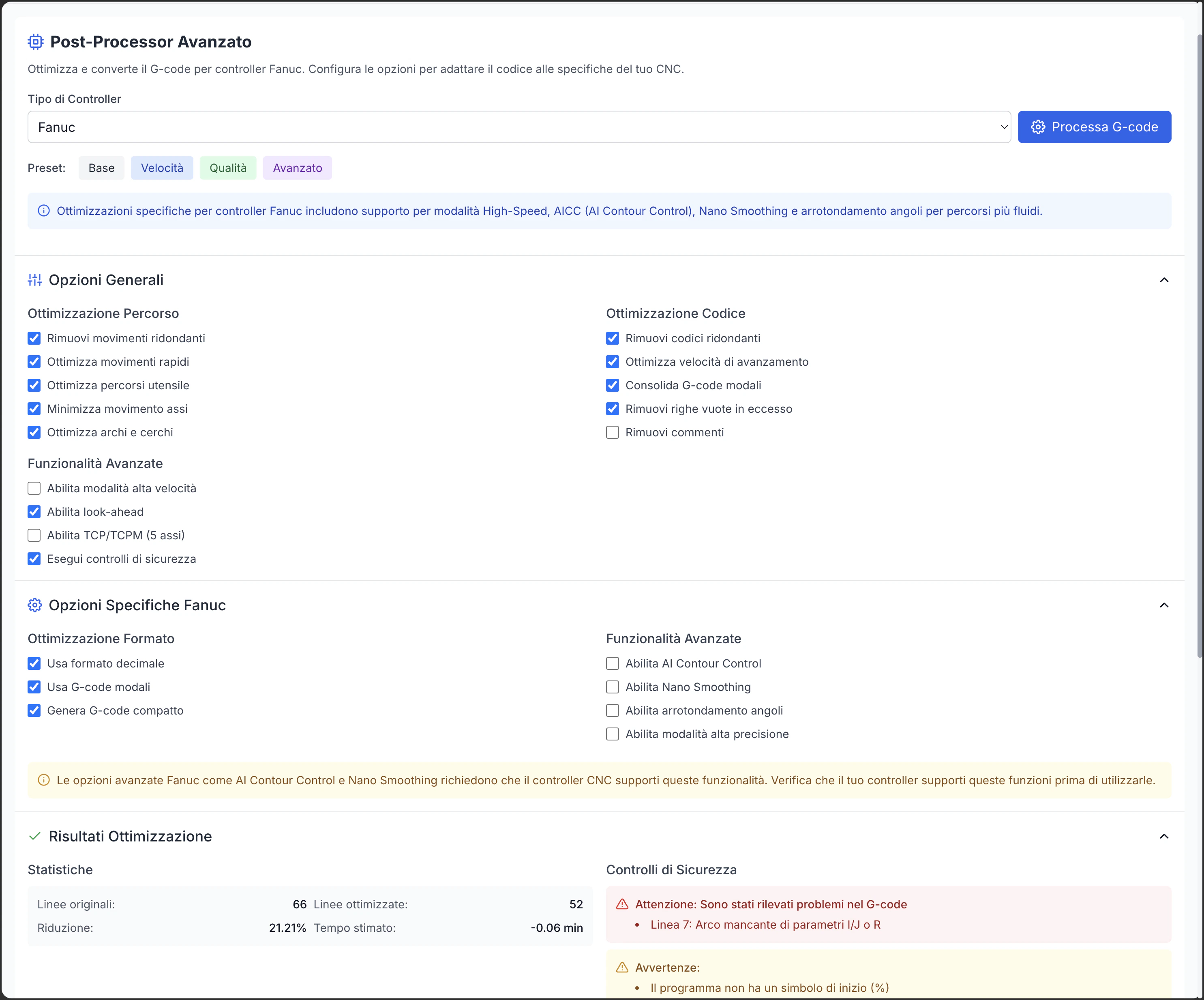
Post-Processor Selection
Supported Controllers
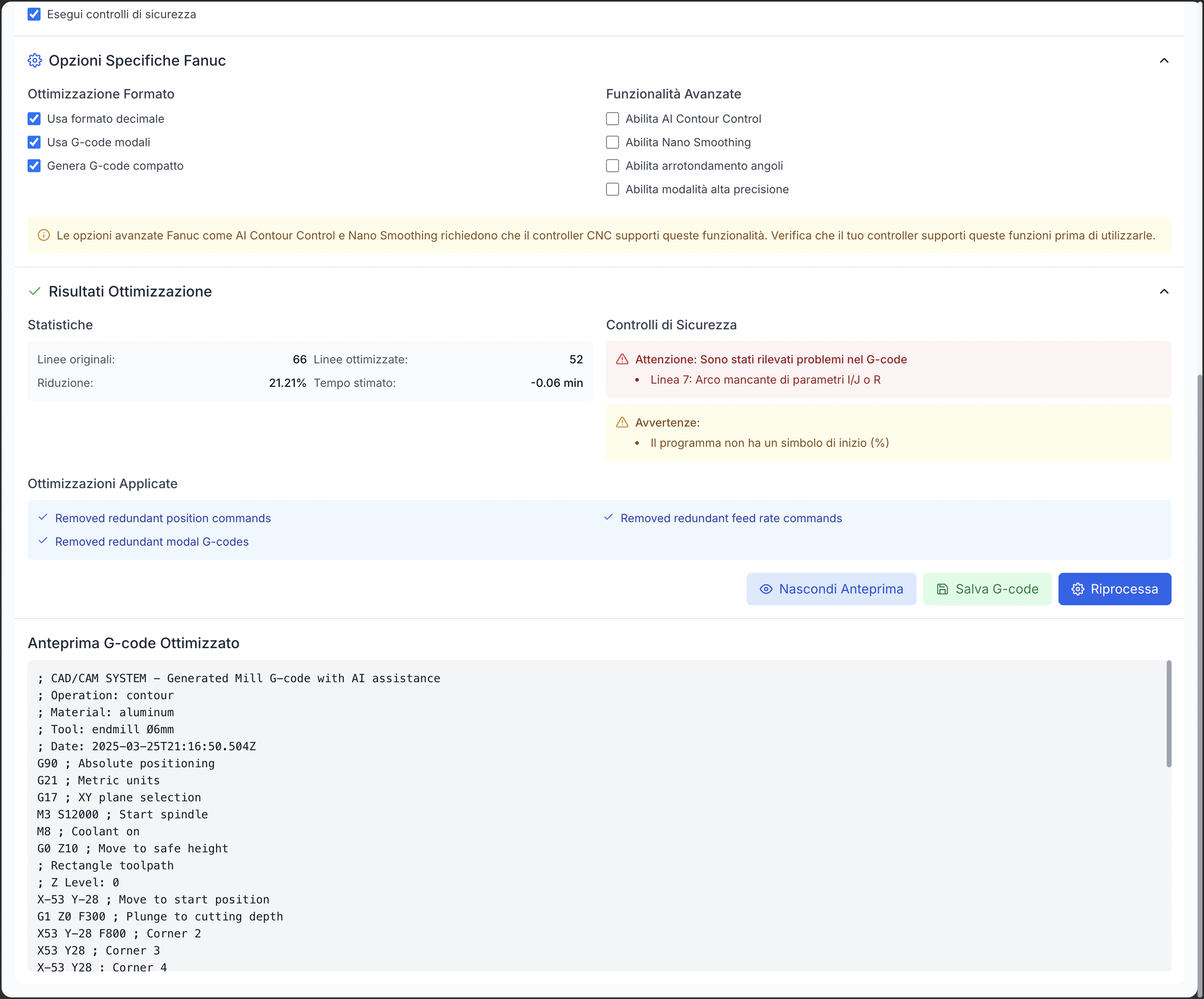
Supported Controllers
- Fanuc: 0i, 16i, 18i, 21i, 30i, 31i, 32i series
- Heidenhain: TNC 320, 620, 640, iTNC 530
- Siemens: Sinumerik 802, 808, 828, 840D
- Haas: Standard and NGC controllers
- Mazak: Mazatrol and EIA/ISO
- Okuma: OSP-P300, OSP-P200
- Mitsubishi: M700, M800
- Fagor: 8055, 8060, 8065, 8070
- Selca: 3000, 4000
- Others: Extensive library of less common controllers
Custom Configuration
Custom Configuration
- Command Customization: Adaptation to specific syntax
- Fixed Cycles: Configuration of available cycles
- Machine Limits: Definition of physical limits
- Hardware Options: Configuration according to installed options
- Specific Commands: Support for proprietary features
- Custom Macros: Integration of machine macros
Controller Version
Controller Version
- Multiple Versions: Support for different firmware releases
- Specific Features: Optimization for available functions
- Backward Compatibility: Support for older versions
- Advanced Features: Utilization of features of newer versions
- Regular Updates: Support for new versions
- Compatibility Testing: Verification of compatibility
Machine Options
Machine Options
- Rotary Axes: Configuration of 4th and 5th axes
- Tool Changer: Type of tool changer system
- Probe: Presence and type of probing system
- Coolant: Available coolant options
- Tool Length Compensation: Tool length compensation system
- Advanced Options: Installed special features
Post-Processing Options
Numeric Format
Numeric Format
- Coordinate Precision: Number of decimal places for positional values
- Feed Precision: Number of decimal places for feed rates
- Numeric Format: With/without leading or trailing zeros
- Decimal Separator: Dot or comma depending on configuration
- Scientific Notation: Enable for very large or small numbers
- Rounding: Value rounding mode
Header and Footer
Header and Footer
Macros and Subroutines
Macros and Subroutines
- Subroutines: Creation of callable routines
- Parametric Macros: Generation of variable macros
- Repeated Calls: Code optimization for repetitive tasks
- Conditional Logic: IF-THEN structure generation
- Loops: Creation of loops for repetitive operations
- Local/Global Variables: Management of variable scope
Comments
Comments
Block Labeling
Block Labeling
- Sequential Numbering: Progressive numbering of blocks
- Customizable Increment: Configurable numbering step
- Operation Labels: Identifiers for different operations
- Resume Points: Labels for specific resume points
- Cross-references: Links between main program and subroutines
- Formatting: Alignment and presentation style
G-code Validation
Syntax Check
Syntax Check
- Error Checking: Verification of syntax errors
- Unsupported Commands: Identification of incompatible commands
- Missing Parameters: Verification of required parameters
- Out-of-Range Values: Check of parameter and coordinate limits
- Structural Errors: Verification of routine and macro balance
- Warnings and Suggestions: Notification of potential issues
Code Analysis
Code Analysis
- Path Optimization: Identification of non-optimal movements
- Frequent Tool Changes: Notification of excessive tool changes
- Redundant Movements: Identification of duplicate paths
- Axis Utilization: Analysis of available axis usage
- Critical Parameters: Verification of feed rates, speeds, and accelerations
- Improvement Suggestions: Proposals for optimization
Code-Based Simulation
Code-Based Simulation
- Direct Simulation: Virtual execution of generated G-code
- Movement Verification: Control of actual machine movement
- Parameter Verification: Actual application of parameter values
- Expanded Cycles: Detailed view of fixed cycles
- Step-by-Step Execution: Analysis of each block
- Special Command Verification: Verification of advanced commands
G-code Optimization
G-code Optimization
- Compaction: Reduction of program size
- Redundancy Removal: Elimination of unnecessary commands
- Path Optimization: Improvement of connections
- Angle and Fillet Handling: Optimal management of angles and transitions
- Controller Adaptation: Optimization for specific characteristics
- Performance/Quality Balance: Configuration based on priorities
Export and Documentation
NC File Export
NC File Export
- Machine Formats: Generation in required controller formats
- Appropriate Extensions: Use of appropriate file extensions (nc, cnc, pim, h, etc.)
- Character Encoding: Support for specific encodings
- File Splitting: Creation of multiple files for long programs
- Interface Compatibility: Adaptation to data transfer systems
- Final Check: Automatic verification before saving
Documentation Generation
Documentation Generation
- Setup Sheets: Information for preparing the machine
- Tool List: Details of required tools
- Parameter Tables: Summary of machining parameters
- Drawings and Schematics: Visualizations of the piece and setup
- Operative Notes: Specific instructions for the operator
- Quality Control: Instructions for checks during machining
Machining Reports
Machining Reports
- Time Analysis: Estimated times for operation and totals
- Tool Utilization: Tool usage and remaining life
- Material Usage: Estimated material removed and residual
- Actual Parameters: Values actually used in the program
- Comparison with Estimates: Verification of initial estimates
- Graphical Representations: Visualization of statistics and paths
Multiple Program Management
Multiple Program Management
- Multiple Programs: Management of related program sets
- Execution Sequence: Definition of execution order
- Links between Programs: References to related programs
- Programs for Different Setups: Organization for machining phases
- Versioning: Management of different versions of the same program
- Program Library: Organization of program libraries
AI Toolpath Optimizer Integration
The AI Toolpath Optimizer uses artificial intelligence algorithms to improve toolpaths: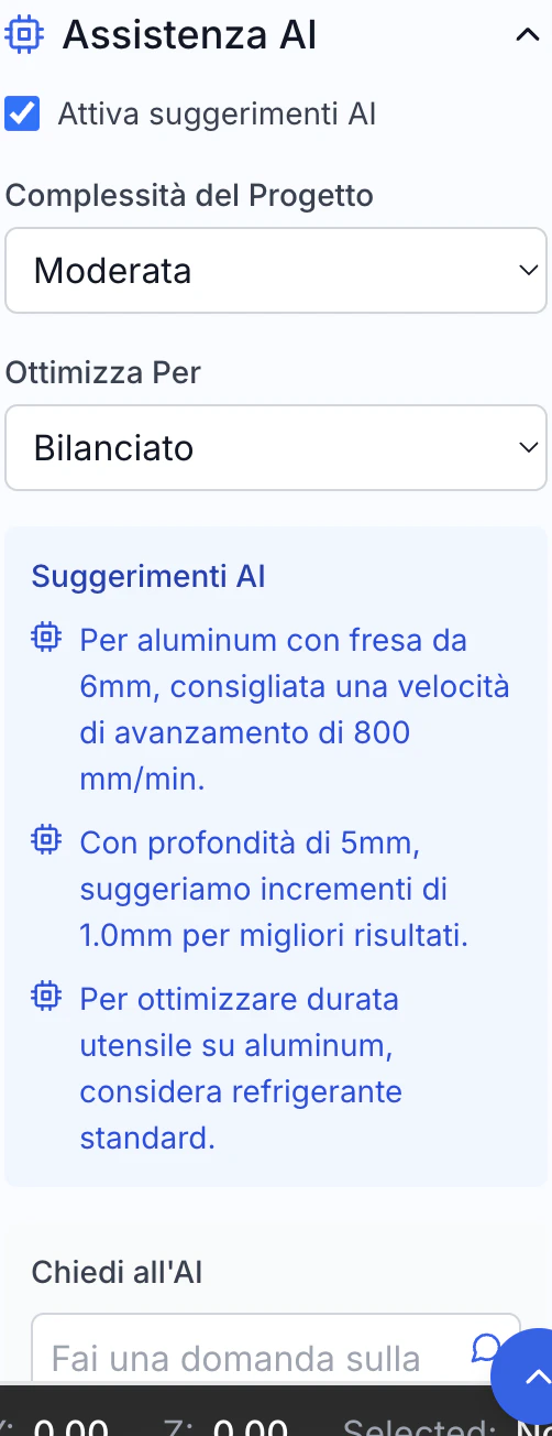
AI Optimizer Features
Automatic Analysis
Automatic Analysis
- Path Scanning: Analysis of the entire toolpath
- Pattern Recognition: Recognition of patterns and schemes
- Efficiency Evaluation: Analysis of efficiency and quality
- Critical Points: Identification of problem areas
- Advanced Analysis: Evaluation of speeds, feeds, accelerations
- Diagnostics: Identification of potential improvements
Multi-parameter Optimization
Multi-parameter Optimization
- Multiple Objective Optimization: Balance of different objectives
- Priority Weighting: Configuration of relative importance
- Scenario Simulation: Test of alternative configurations
- Compromise Solution: Identification of best balance
- Impact Assessment: Measure of effect on different parameters
- Result Prediction: Estimation of final result
Adaptive Learning
Adaptive Learning
- Learning from Results: Improvement from past experiences
- Historical Database: Use of data from previous machining
- Continuous Refinement: Progressive improvement over time
- User Customization: Adaptation to specific preferences
- Contextual Learning: Understanding of machining context
- Collective Improvement: Benefit from all users’ experience
Custom Strategy
Custom Strategy
- Machining Profiles: Configurations for different types of machining
- Specific Goals: Optimization targeted to specific results
- Custom Constraints: Consideration of specific limitations
- Machine Adaptation: Optimization for machine characteristics
- User Preferences: Respect for preferred approaches
- Use Cases: Configurations for specific sectors and applications
Optimization Goals
Machining Time Reduction
- Optimization of connecting movements
- Reduction of redundant movements
- Configuration of optimal speeds and accelerations
- Grouping of similar operations
- Minimization of tool changes
Surface Finish Improvement
- Uniformity of passes and stock
- Speed control in curves and details
- Optimization of entry and exit angles
- Uniformity of tool load for stability
- Minimization of vibrations and deflections
Tool Life Extension
- Control of constant loads
- Progressive entries and exits
- Uniform load distribution
- Coolant optimization
- Prevention of overheating
Energy Efficiency
- Minimization of power peaks
- Optimization of accelerations and braking
- Reduction of unnecessary movements
- Axis usage balancing
- Reduction of idle times
Goal Combination
- Configuration of goal balance
- Predefined profiles for typical cases
- Contextual optimization (roughing vs. finishing)
- Adaptation to specific project requirements
- Consideration of production constraints
Speed/Quality Balance
- Requirements analysis: Understand real tolerance and finish needs
- Differentiated strategies: Use different approaches for roughing and finishing
- Selective finishing: Apply high quality only where necessary
- Progressive testing: Incrementally verify results
- Operator feedback: Gather input from machine operators
- Continuous improvement: Constantly refine programs
Using the Optimizer
Starting Optimization
- Choose one or more operations to optimize
- Access optimizer from context menu or AI panel
- Verify path is valid and ready for optimization
Setting Goals
- Configure relative importance of different goals
- Set specific constraints to respect
- Choose predefined profile or create custom configuration
- Define relevant machine parameters
Comparative Analysis
- View paths side by side for visual comparison
- Examine comparative statistics (time, quality, etc.)
- Verify expected improvement for each goal
- Explore specific changes made
Feedback and Improvement
Results Evaluation
Results Evaluation
- Quantitative Metrics: Measurement of improvement in time, quality, etc.
- Visual Comparison: Visualization of differences
- Comparative Simulation: Test of performance
- Path Evaluation: Analysis of modified paths
- Detailed Statistics: Data on various optimization aspects
- Change Report: Documentation of changes made
AI Parameter Adjustment
AI Parameter Adjustment
- Goal Weighting: Modification of relative importance
- Change Aggressiveness: Control over degree of intervention
- Specific Constraints: Definition of particular limitations
- Custom Profiles: Saving of preferred configurations
- Advanced Parameters: Access to detailed settings
- Default Reset: Restoration of standard configuration
Learning from Previous Cases
Learning from Previous Cases
- Results Database: Archive of previous optimizations
- Pattern Analysis: Identification of recurring patterns
- Failure Prediction: Estimation of component remaining life
- Scheduled Maintenance: Planning of interventions
- Cycle Optimization: Adaptation to reduce stress
- Preventive Alerts: Warnings before failures
Machine Cycles and Automation
Machine cycles simplify the programming of common operations:Available Cycle Types
Drilling Cycles
- Cycles for through or blind holes
- Deep drilling with incremental retracts
- Peck cycles for chip evacuation
- Tapping cycles with or without compensation
- Precision boring and reaming
- Specific cycles for different controllers
Tapping Cycles
- Synchronized cycles for rigid tapping
- Compensated tapping for floating holders
- Cycles for right or left-hand threads
- Variable pitch tapping
- Multi-pass tapping cycles
- Optimized entry and exit strategies
Milling Cycles
- Pocket clearing with or without islands
- Groove and slot milling
- Circular milling cycles
- Inclined bottom pocket machining
- Plunge milling for difficult materials
- Optimized milling patterns
Turning Cycles
- Parallel or profile roughing cycles
- External and internal surface finishing
- Constant pitch external and internal threading
- Tapered or variable pitch threading
- Grooving and parting cycles
- Advanced turning strategies
Custom Cycles
- Creation of combined custom cycles
- Parameterization of existing cycles
- Specific cycles for special processes
- Incorporation of proprietary strategies
- Cycles optimized for specific materials
- Solutions for complex geometries
Cycle Parameters
Geometry
Geometry
- Main Dimensions: Diameters, depths, widths
- Positioning: Reference coordinates and orientation
- Profiles: Definition of contours for profiling cycles
- Patterns: Arrangement for groups of similar features
- Reference Geometry: Elements for relative positioning
- Tolerances: Specification of required precision
Depth
Depth
- Total Depth: Overall machining distance
- Incremental Depth: Value of each increment
- First Depth: Specific value for first increment
- Return: Return height between increments
- Bottom Stock: Material left on bottom
- Variable Increment: Progression of increments
Feed Rate
Feed Rate
- Working Feed: Speed during cutting
- Entry Feed: Speed during material entry
- Exit Feed: Speed during material exit
- Rapid Feed: Quick movements outside material
- Feed Override: Modifiers for specific cases
- Different Phase Feeds: Different values for roughing/finishing
Coolant
Coolant
- On/Off Control: Control in specific phases
- Coolant Type: Selection of cooling channel
- Pressure: Control of pressure for specific operations
- Timing: Early activation for pre-cooling
- Chip Evacuation: Programmed cleaning cycles
- Targeted Cooling: Control of specific nozzles
Ritorno
Ritorno
- Piano di ritorno: Altezza di sicurezza per movimenti
- Ritorno incrementale: Ritiro parziale tra incrementi
- Ritorno completo: Ritorno al piano di sicurezza
- Comportamento fine ciclo: Posizione finale dopo il ciclo
- Velocità di ritorno: Controllo velocità movimenti di ritorno
- Pattern di ritorno: Traiettoria di uscita dal materiale
Parametric Programming
Variables
Variables
- Global Variables: Accessible throughout the program
- Local Variables: Limited to specific routines
- System Parameters: Controller predefined variables
- Arrays: Collections of related values
- Tables: Organized data structures
- Persistence: Value retention between executions
Mathematical Expressions
Mathematical Expressions
- Arithmetic Operations: Addition, subtraction, multiplication, division
- Mathematical Functions: Trigonometry, root, power, etc.
- Conversions: Between different units and systems
- Rounding: Control of precision
- Advanced Functions: Statistics, interpolations, etc.
- Constants: Predefined mathematical values (π, e, etc.)
Flow Control
Flow Control
- IF-THEN-ELSE Structures: Conditional execution
- WHILE Loops: Repetitions based on condition
- FOR Loops: Repetitions with counter
- Conditional Jumps: GOTO based on conditions
- Error Handling: Response to abnormal conditions
- Nesting: Nested control structures
Subroutines
Subroutines
- Routine Definition: Creation of reusable blocks
- Parameter Passing: Data transfer to subroutine
- Return Values: Recovery of results from subroutine
- Nested Calls: Subroutines calling other subroutines
- Recursion: Subroutines calling themselves
- Libraries: Collections of reusable subroutines
Custom Macros
Custom Macros
- Macro Creation: Definition of custom sequences
- Parameterization: Configuration through parameters
- Compilation: Conversion to optimized code
- Macro Libraries: Organization and reuse
- Documentation: Description of functionality and parameters
- Versioning: Management of different versions
Process Automation
Operation Sequences
Operation Sequences
- Predefined Workflows: Sequences of typical operations
- Cycle Concatenation: Smooth linking between different cycles
- Transition Optimization: Efficient movements between operations
- Tool Management: Optimal sequence to minimize changes
- Dependent Operations: Sequences conditioned by results
- Feedback Loop: Adaptation based on measurements
Machining Templates
Machining Templates
- Template Library: Collection of optimized configurations
- Customization: Adaptation of templates to specific needs
- Quick Application: Fast implementation of best practices
- Material-specific Configurations: Templates optimized for materials
- Industry Templates: Configurations for specific industries
- Sharing: Exchange of templates between users
Automation Scripts
Automation Scripts
- Scripting Language: Creation of high-level programs
- Machine API: Access to advanced controller features
- Sensor Integration: Response to real-time sensor data
- Automatic Decisions: Advanced process logic
- Exception Handling: Response to non-standard events
- Automatic Documentation: Recording of executed operations
Production System Integration
Production System Integration
- Order Reception: Program generation from production orders
- Reporting: Sending production data to management systems
- Traceability: Recording of actual parameters and times
- Resource Management: Coordination with tool and material availability
- Planning: Integration with scheduling systems
- Quality: Connection with quality control and metrology
Machine Control
The machine control panel allows direct communication with the CNC machine: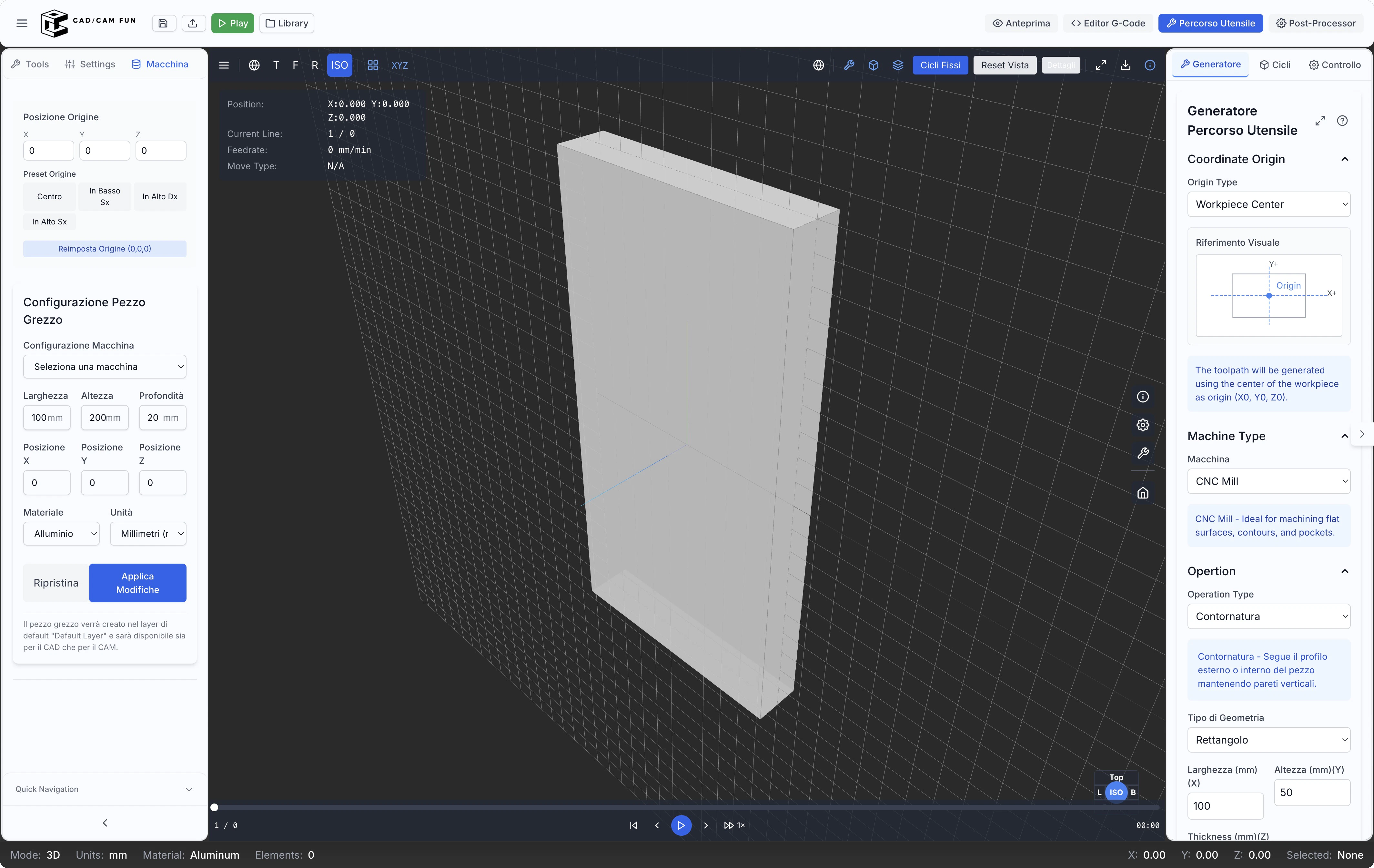
Machine Connection
Supported Protocols
Supported Protocols
- Ethernet: Standard network connection
- USB: Direct connection via USB port
- Serial: RS-232 connection for older machines
- Wireless: Wi-Fi or Bluetooth connection
- Proprietary systems: Manufacturer-specific protocols
- Cloud connection: Through industrial cloud solutions
DNC Control
DNC Control
- Program sending: Direct transfer to CNC control
- Drip feeding: Progressive transfer for large programs
- Transfer verification: Data integrity check
- Feedback reception: Transfer status monitoring
- Library management: Program storage on machine
- Synchronization: Maintaining consistency between CAM and machine
Status Monitoring
Status Monitoring
- Axis position: Current coordinates of all axes
- Operational status: Running, paused, alarm
- Active parameters: Spindle speed, current feed rate
- Axis load: Monitoring of axis and spindle effort
- Program progress: Completion percentage
- Times: Elapsed and estimated completion time
Override
Override
- Feed override: Feed rate adjustment
- Spindle override: Rotation speed control
- Rapid override: Rapid movement speed adjustment
- Pause/Resume: Program execution control
- Single block: One block at a time execution
- Feed hold: Temporary feed stop
Origin and Reference Management
Workpiece Zero Setting
Workpiece Zero Setting
- Manual methods: Guides for manual setup
- Probing cycles: Automatic procedures with probe
- Feature recognition: Automatic reference identification
- Alignment: Correction of workpiece misalignment
- Multiple systems: Management of multiple origins
- Compensations: Automatic offset application
Tool Preset Management
Tool Preset Management
- Length measurement: Precise length determination
- Diameter measurement: Actual diameter verification
- Tool database: Archive of measured tool data
- Automatic compensations: Corrective offset application
- Wear monitoring: Tracking of dimensional variations
- Off-line presetting: Integration with external systems
Probing Cycles
Probing Cycles
- Point probing: Single point detection
- Edge probing: Precise edge identification
- Hole probing: Center and diameter determination
- Island probing: Measurement of raised features
- Surface probing: Surface orientation determination
- Automatic alignment: Workpiece positioning correction
Multiple Coordinate Systems
Multiple Coordinate Systems
- Multiple work offsets: Definition of various reference systems
- Machine coordinates: Absolute machine reference
- Fixture coordinates: Specific fixture references
- Programmable coordinates: Systems defined in program
- Transformations: Conversions between different systems
- Coordinate rotations: Rotated systems for multi-axis machining
Program Execution
Start/Stop
Start/Stop
- Program start: Begin execution
- Programmed stop: Orderly completion
- Emergency stop: Immediate interruption
- Restart: Resume from specific point
- Block start: Execution from selected block
- Conditional execution: Start based on conditions
Single Block Mode
Single Block Mode
- Step-by-step advance: Granular control
- Real-time verification: Analysis of each operation
- Block pause: Time for checks
- Block skip: Possibility to skip specific steps
- Block loop: Repetition of specific sequences
- Detailed analysis: In-depth operation verification
Feed Override
Feed Override
- Percentage control: Percentage adjustment
- Dynamic variation: Context-based adaptation
- Safety limits: Prevents dangerous values
- Presets: Default values for specific situations
- Override profiles: Pre-programmed variation sequences
- Selective override: Application to specific operations
Auxiliary Functions
Auxiliary Functions
- Coolant on/off: Cooling system control
- Chip evacuation: Cleaning system management
- Workpiece clamping: Fixturing system control
- Pressure control: Pneumatic/hydraulic system adjustment
- Auxiliary systems: Secondary equipment activation
- Signaling: Indicator and alarm control
Diagnostics and Monitoring
Error Display
Error Display
- Error codes: Machine error decoding
- Detailed descriptions: Cause explanation
- Resolution suggestions: Guides to solve problems
- Error history: Previous error log
- Categorization: Organization by type and severity
- Contextual documentation: Access to specific manuals
Load Monitoring
Load Monitoring
- Axis load: Effort visualization on each axis
- Spindle load: Power and torque monitoring
- Real-time graphs: Trend visualization
- Alert thresholds: Warnings for critical values
- Data recording: Storage for analysis
- Path correlation: Load association with geometry
Operation Log
Operation Log
- Detailed log: Complete chronological record
- Event filters: Selective visualization
- Export: Save for external analysis
- Annotations: Adding notes to specific events
- Search: Quickly find specific events
- Statistics: Aggregate data analysis
Predictive Maintenance
Predictive Maintenance
- Wear indicators: Detection of deterioration signals
- Trend analysis: Problem pattern identification
- Failure prediction: Component life estimation
- Scheduled maintenance: Intervention planning
- Cycle optimization: Adaptation to reduce stress
- Preventive alerts: Warnings before failures
Tips and Best Practices for the CAM Editor
Process Optimization
Machining Strategy
Machining Strategy
- Preliminary analysis: Evaluate part characteristics and requirements
- Strategy selection: Identify optimal approach for each feature
- Prioritization: Determine logical operation sequence
- Balancing: Find balance between time and quality
- Material adaptation: Customize based on material to be machined
- Tool optimization: Choose specific tools for each strategy
Operation Sequence
Operation Sequence
- General roughing: Initial removal of excess material
- Pre-finishing: Preparation for finishing operations
- Internal details: Machining of pockets and internal features
- Holes and threads: Drilling/tapping operations
- Contouring: External edge profiling
- Final finishing: Operations for surface quality
Cutting Parameters
Cutting Parameters
- Consult catalogs: Use manufacturer recommendations
- Consider machine: Adapt parameters to available rigidity and power
- Specific material: Customize for material type and hardness
- Finish optimization: Adjust parameters for desired quality
- Productivity/life balance: Find balance between speed and tool life
- Critical parameter verification: Always check values before generating code
Validation
Validation
- Complete simulation: Verify entire program before execution
- Collision check: Verify absence of interference with fixtures
- Critical area analysis: Carefully examine complex areas
- Parameter verification: Check speeds and feeds at critical points
- Time estimation: Evaluate total process duration
- Residual material verification: Check that all necessary material is removed
Tool Management
Organized Library
Organized Library
- Logical categorization: Organize by type, size, use
- Consistent naming: Use clear naming system
- Complete data: Enter all relevant parameters
- Documentation: Add notes on performance and applications
- Regular update: Keep library current with new purchases
- Backup: Create library backup copies
Tool Life
Tool Life
- Usage tracking: Record operating times and wear
- Replacement planning: Schedule changes before failure
- Regular inspection: Visual wear check
- Sharpening: Plan restoration interventions
- Performance analysis: Evaluate effectiveness of different tools
- History: Maintain data on duration in different conditions
Standardization
Standardization
- Inventory reduction: Limit variety of tools to manage
- Interchangeability: Simplify replacement when needed
- Cost optimization: Improve economies of scale in purchases
- Programming simplification: Reduce program complexity
- Focused inventory: Concentrate resources on fundamental tools
- Consolidation: Eliminate similar and redundant tools
Path Optimization
Path Optimization
- Operation grouping: Execute all operations per tool
- Multifunction tools: Use versatile tools for different operations
- Setup analysis: Evaluate impact of tool changes on times
- Prioritization: Organize operations to minimize changes
- Balancing: Consider both efficiency and tool wear
- Comparative testing: Evaluate different sequences to find optimal
Safety and Reliability
Collision Check
Collision Check
- Complete simulation: Analyze entire tool path
- Tool holder consideration: Include entire assembly in verification
- Fixturing: Accurately model clamps and fixtures
- Full stroke consideration: Verify entire work volume
- Adequate safety heights: Use margins appropriate to setup
- Manual verification: Visually examine critical areas
Safe Approaches
Safe Approaches
- Gradual entry: Progressive approach to material
- Adequate safety heights: Maintain sufficient distances
- Intermediate points: Use safe transition points between operations
- Complete retracts: Fully extract tool from risky areas
- Controlled movements: Avoid sudden direction changes
- Path verification: Carefully simulate entries and exits
Program Backup
Program Backup
- Versioned archive: Keep different versions with clear identifiers
- Change documentation: Note what changes between versions
- Multiple backups: Keep copies on different media
- Logical organization: Clear structure of archiving system
- Complete metadata: Add information about setup, required tools, etc.
- Periodic testing: Regularly verify backup accessibility
Incremental Testing
Incremental Testing
- Single block: First execution in single block mode
- Reduced speed: Start with low feed override
- Visual verification: Check first steps carefully
- Programmed interruptions: Insert pauses for inspections
- Intermediate measurements: Verify dimensions during process
- Progressive increase: Gradually increase to full regime
Productivity
Machining Templates
Machining Templates
- Standard operations: Save optimized configurations for common operations
- Material-specific setup: Templates dedicated to different materials
- Predefined sequences: Series of pre-ordered operations
- Tested parameters: Values already verified in the field
- Integrated documentation: Notes and explanations included in template
- Organized catalog: Accessible library of templates for different cases
Automation
Automation
- Custom scripts: Create automations for recurring operations
- Feature recognition: Use automatic geometry recognition
- Predefined rules: Define standard behaviors for common situations
- Batch processing: Process groups of operations simultaneously
- Machine cycles: Leverage machine fixed cycles
- Flow integration: Connect CAD, CAM, and machine seamlessly
Combined Operations
Combined Operations
- Multi-axis machining: Use 4/5 axes to access multiple faces
- Multiple fixtures: Configure multiple parts simultaneously
- Optimized sequences: Organize to minimize setup changes
- Universal tools: Use versatile tools for different operations
- Consolidation: Combine similar operations when possible
- Assisted setup: Use probes to speed up setup changes
Speed/Quality Balance
Speed/Quality Balance
- Requirements analysis: Understand real tolerance and finish needs
- Differentiated strategies: Use different approaches for roughing and finishing
- Selective finishing: Apply high quality only where necessary
- Progressive testing: Incrementally verify results
- Operator feedback: Gather input from machine operators
- Continuous improvement: Constantly refine programs
The CAM Editor provides you with all the necessary tools to transform your CAD projects into optimized toolpaths and production-ready G-code. In the next section, we will explore project management in more detail.
- Operation Comments: Description of each operation
- Tool Comments: Details about the current tool
- Parameter Comments: Explanation of used parameters
- Section Delimiters: Logical division of the program
- Operator Notes: Instructions for the operator
- Comment Syntax: Adaptation to controller syntax
Comments improve readability and facilitate understanding and modification of the code.